
Based on the accuracy standard, combined with the structural constraints of large energy machinery and equipment and the requirements of normal meshing transmission of herringbone gear, the machining accuracy of herringbone gear is generally controlled within level 6. However, since the symmetry of the left and right tooth surfaces of herringbone gears needs to be ensured by manual scribing, the process is cumbersome, and the machined centering error is large. Generally, it can only be controlled within grade 8 accuracy. When the gear size is large, the accuracy of herringbone gears can only be controlled within grade 10, resulting in uneven gear meshing marks and high noise [16]. In this paper, the geometric model of herringbone gear pair is taken as the centering error based on the parameters shown in Table 1 ζ For 0.05 mm, 0.1 mm, 0.15 mm and 0.2 mm, the herringbone gear system with different centering errors is analyzed based on ANSYS.
In the dynamic contact analysis, the gear pair working conditions, finite element boundary conditions and constraints are still set according to the relevant parameters described in Section 1. The contact stress nephogram of herringbone gear tooth surface with different centering errors is shown in the figure.
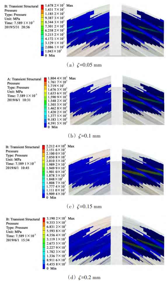
Through the above four groups of herringbone gear contact stress nephogram with different centering errors, it can be found that the tooth surface contact stress is distributed on the adjacent four teeth. Theoretically, the herringbone gear pair is in line contact in the meshing process, but the actual meshing process is affected by the elastic deformation of tooth surface and bearing deformation, so that the contact line becomes an approximate contact ellipse. Due to the existence of alignment error, the initial clearance between the left and right tooth surfaces is different, resulting in the asymmetric distribution of the contact stress of the helical gears at both ends, resulting in the left and right eccentric load of the herringbone gear, and the position of the contact stress also moves to the side of the eccentric load. With the increase of alignment error, the tooth contact stress at the eccentric load end also increases, and the gear pair is easy to exceed its material strength limit at the beginning of meshing movement, so as to reduce the service life and strength of the gear.