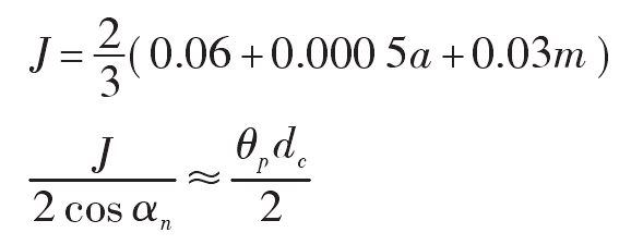
As shown in Figure 1, OC is the center of gear shaper cutter, G is any point on the initial involute 1, point K is on the base circle, and the intersection of OC ⊥ kg and indexing circle is at point C, and point P is the initial meshing point. Let the involute spread angle ∠ GOCE= θ k. Pressure angle ∠ KCG= α k,∠c Oce = θ c, ∠kOcc = θ , If we also know that OCC = h and ock = DCB2, we can get the formula, where the coordinate of point C is (XC, YC). When the rolling distance is equal to the arc length PC, the rotation angle of the gear shaper cutter is equal to ∠ C OCP, and the point G is the meshing point at this time. The more the meshing points are, the more accurate the tooth profile is.
Rotation angle of gear shaper cutter θ ZZ = ∠ C OCP, calculated according to the formula; The arc length of PC section is calculated according to the formula.
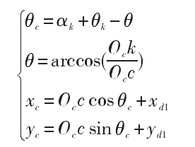
The single tooth profile of gear shaper cutter is shown in Fig. 2, ϕ =π/ 2zc, involute 2 is the symmetrical line of involute 1 about straight line 3, and involutes 1 and 2 are the single tooth profile of gear shaper cutter for driving non-circular gear.
The gear shaping process of driving non-circular gear is shown in Fig. 3. When the pitch circle of the gear shaper cutter is rolling along the pitch curve, the profile 1 and 2 of the gear shaper cutter will produce the profile 1z and 2Z of the driving non-circular gear respectively. In order to make the tooth side clearance exist in the meshing process of the driving and driven non-circular gears, the profile 1 of the gear shaper cutter is rotated clockwise by a small angle around the center OC of the gear shaper cutter θ p. The profile 1p is formed, and the profile 1p will produce the profile 1pz.
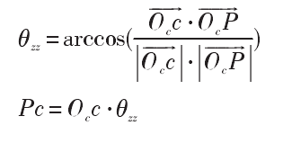
As shown in Figure 4, the tangent passing through point P is tangent to the pitch curve of the driving and driven noncircular gears at the same time. After the tooth profiles 1 and 2 of the gear shaper cutter of the driving non-circular gear are tangent symmetrical, the tooth profiles 1 ‘and 2’ are obtained, and OC ‘is the center of the gear shaper cutter; Rotate 1 ‘and 2’ clockwise around OC ‘ π/ ZC rad to obtain the profile I and II of the gear shaper cutter of the driven non-circular gear.

The gear shaping process of driven non-circular gear is shown in Figure 5. When the pitch circle of the gear shaper tool rolls counter clockwise along the pitch curve, the profile I and II of the gear shaper tool will process the profile iz and IIz of the driven non-circular gear respectively. In order to make the driven and driving noncircular gears have backlash in the meshing process, the tooth profile II is rotated clockwise by a small angle around the center OC ‘ θ p. The profile IIP is formed, and the profile IIP will produce the profile iipz.

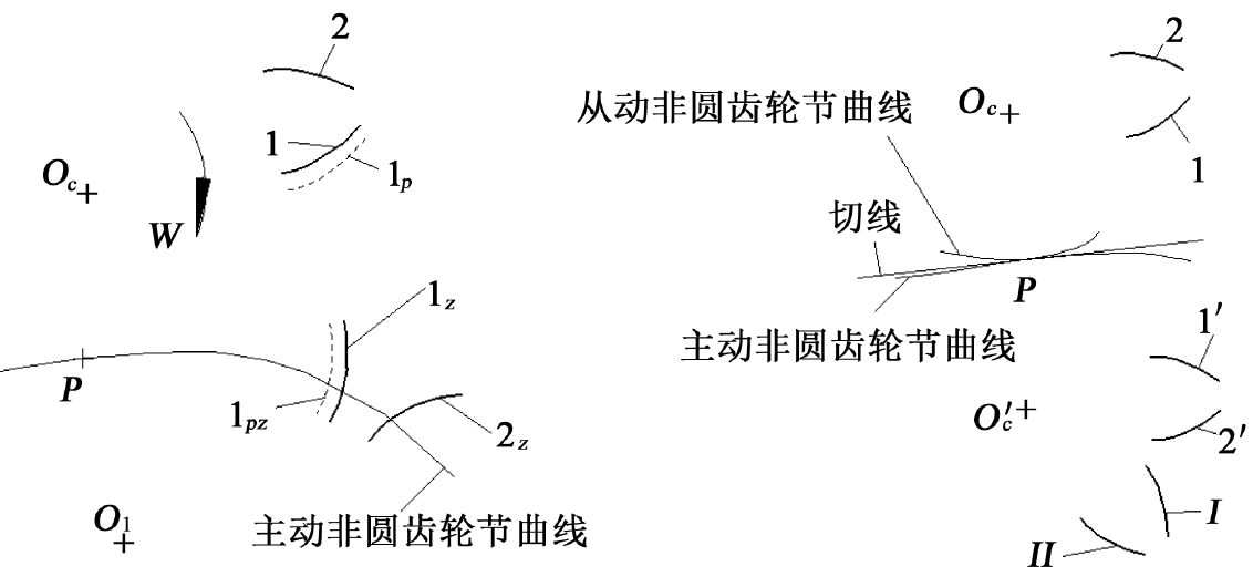
It can be seen from Fig. 3-5 that profile 2 is conjugate with profile 2Z, profile I is conjugate with profile IZ, and profile 2 and profile I are the same profile. According to cams theorem, profile 2Z must be conjugate with profile iz. When the driving noncircular gear rotates counterclockwise, the profile 2Z will drive the profile iz to rotate clockwise, so as to realize the power transmission; At this time, because the tooth thickness of the driving non-circular gear and the driven non-circular gear is thinner, there must be backlash between the non working tooth profiles, which can ensure the gear lubrication and compensate the errors caused by the manufacturing error, installation error and thermal deformation of the gear. According to the recommendation, the backlash J can be calculated according to the formula, and j = 0.08 mm. According to the geometric relationship shown in Figure 6, it can be concluded that θ The calculation formula of P is obtained θ p=0.122 °.