
Study on Lubrication Simulation of Spiral Bevel Gear
The friction force and lubrication of spiral bevel gear contact surface are studied. On the basis of modern mechanical lubrication […]
The friction force and lubrication of spiral bevel gear contact surface are studied. On the basis of modern mechanical lubrication […]
1. Actual meshing line length before trimming The meshing transmission range of a pair of gears is limited, as shown
When selecting the right gear solution for a particular application, it is important to consider the specific requirements, operating conditions,
Heat treatment optimization in gear production involves finding the right balance between performance and cost. Heat treatment is a critical
Bevel gears and internal gears are two common types of gears used in various mechanical systems. While both serve the
According to the meshing characteristics of spur gear, the gear teeth just entering the mesh do not bear the load,
Straight bevel gears are essential components in various mechanical systems, where they play critical roles in power transmission and motion
When it comes to heat treatment for spur gears, helical gears, and bevel gears, there are several key considerations to
The transmission device of locomotive bogie is mostly a first-level spur gear reduction structure and the actual operating speed varies
Gear transmission has the advantages of high power transmission, high efficiency, and accurate transmission ratio, and is widely used in
Chapter 1: The Machining Process of Gear Grinding Gear grinding is a precision machining method used to create accurate and smooth
Chapter 1: The Process Steps of Gear Shaping the gear shaping process is generally accurate, but let me provide a bit
Chapter 1: Gear Hobbing Method Brief overview of two methods of gear hobbing technology: gear hob hobbing and gear roller hobbing.
The advantages and disadvantages of feature extraction can determine the complexity and difficulty of the algorithm. A simple understanding is
The calculation of threshold segmentation is simple and efficient, but the selection of threshold needs to be determined according to
Image enhancement is to improve the image definition. Unlike the original image, image enhancement does not need to completely reflect
Chapter 1: Definition and Basic Concepts of Helical Gears Helical gears are a type of mechanical component commonly used in
In the process of image acquisition, the lighting equipment can not uniformly cover the surface of the spur gear housing,
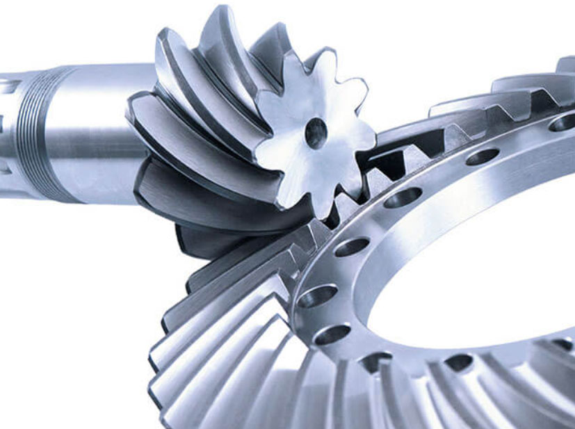
Chapter 1: Definition and Composition of Spiral Bevel Gear A spiral bevel gear is a type of gear system that consists
With the rapid development of the manufacturing industry and the continuous improvement of market demand, the demand and quality of
At the beginning of the new century, Ali needs large bevel gears with higher bending strength when transmitting power on
Bevel gears and spiral gears are two common types of gears used in various mechanical systems. Both gear types have
Herringbone gears and internal gears are both types of gears used in mechanical systems, but they have distinct characteristics and
Herringbone gears and miter gears are both types of gears commonly used in mechanical systems. While they serve similar functions,
Gear grinding and gear cutting are two essential methods used in gear manufacturing, each with distinct characteristics, advantages, and applications.
China is a big country in automobile manufacturing. Under the background of rapid social and economic development in China, the
(1) Increase the research on manufacturing large diameter spiral bevel gears It is necessary to introduce the advanced spiral tooth
(1) Traditional processing technology The traditional processing method of spiral bevel gear is to use special disc milling cutter to
Advancements in helical gear technology have been significant, driven by continuous research, innovation, and improvements in design, manufacturing processes, and
Since the beginning of the 21st century, the process of national modern industrialization has accelerated, and the heavy industry has
Helical gears play a crucial role in medical equipment, ensuring smooth and reliable operation in various healthcare applications. The medical
Spiral bevel gear is a concept relative to straight bevel gear and helical bevel gear. It is a key part
Spiral bevel gears play a vital role in marine applications, where they are subjected to demanding conditions on the open
Selecting the right material is crucial for high-load helical gear applications to ensure durability, strength, and resistance to wear and
Thermal effects can significantly impact the performance and reliability of helical gears, particularly in applications where high temperatures or temperature
Tooth width is usually regarded as an effective measure to improve gear strength, but in the actual design process, when
Helical gears play a vital role in marine propulsion systems, meeting the demanding environments and requirements of marine applications. Marine
As the end of the gear transmission chain, the load of each accessory directly affects the strength, connection reliability, lubrication
Noise reduction in helical gear systems is essential to create quieter and more comfortable operating environments in various applications. Helical
Designing helical gears for low backlash and high precision requires careful consideration of several factors related to gear geometry, material
Analyzing helical gear meshing is essential to ensure optimal performance and reliable operation of gear systems. The analysis involves assessing
Gear shaping, as a fundamental process in gear manufacturing, has seen several innovations and advancements that have significantly improved the
Spur gears serve as the cornerstone of gear systems in various industries, providing efficient power transmission, reliable motion control, and

Spiral bevel gears combine the characteristics of both spiral gears and bevel gears. They consist of a helical gear and
The dynamic characteristics of the gear system mainly include gear strength, connection reliability, lubrication characteristics, etc. Among them, the gear
Addressing thermal effects in spiral bevel gear systems is crucial to ensure the gears’ reliable performance and prevent premature failure
Hypoid gears play a critical role in aviation applications, enabling safer and smoother flight in both commercial and military aircraft.
When considering the choice between hypoid gears and helical gears, it’s important to assess the specific requirements and characteristics of
Helical gears play a significant role in renewable energy systems, contributing to the efficient and reliable conversion of renewable energy
Helical gears are widely used in heavy-duty industrial machinery, where robustness, efficiency, and reliability are paramount. Their unique design features
Straight bevel gears and helical gears are both common types of gears used in various applications, but they have distinct
Custom worm gears play a significant role in aerospace actuation systems, providing precise and reliable motion transfer for various components
Proper lubrication is essential for ensuring the longevity and efficiency of custom worm gears. Lubrication reduces friction, wear, and heat
1. Parameters of complete machine and gear Cylinder diameter/mm Stroke/mm Number of cylinders Rated power/kW Maximum torque / (N ·
Optimizing spiral bevel gear pairings is essential to achieve smooth operation, minimize noise and vibration, and ensure the longevity of
The mechanics of hypoid gear meshing involve the interaction of the gear teeth as they come into contact during operation.
Designing hypoid gears for maximum load capacity and durability involves careful consideration of various design parameters and material choices. Here
Reliability is one of the key points in the engine development process, and the reliability of gear system plays an
Helical gears play a critical role in aerospace applications, where reliability, efficiency, and precision are of utmost importance. The aerospace
Straight bevel gears play a vital role in marine propulsion systems, where they are used to transmit power from the