Straight bevel gears are essential mechanical components that transmit torque through the meshing of the tooth profiles of gears, similar to the function of straight cylindrical gears. However, compared to straight cylindrical gears, bevel gears have several advantages. Firstly, the installation axis of bevel gears can be at any angle between 0° and 90°. Secondly, bevel gears operate more smoothly and transmit more torque than cylindrical straight gears. Thirdly, the modulus of straight bevel gears varies from one end of the full tooth width to the other.
Bevel gears are also used in pairs. When inspecting gear components, some inspection parameters are required for individual gears, such as tooth height, common normal length, chordal tooth thickness, etc., while other parameters can only be inspected when the gears are paired and meshed, such as subtended angle detection, shaft intersection angle detection, contact spot detection, tooth surface backlash detection, and tooth tip clearance detection, etc.
If paired gears are assembled on the product without undergoing pairing inspection and problems are found in the tooth surface meshing, disassembly can be quite cumbersome. This is because generally, straight bevel gears and the matching transmission shafts are assembled through interference or transition fits by means of hot or cold installation, with a relatively tight fit. Secondary disassembly is more troublesome. Therefore, it is necessary to design a tooling for bevel gear meshing to inspect the detection elements under the gear meshing condition in advance.
1. Product Introduction
Our company is one of the main manufacturers of rubber and plastic machinery in China, including internal mixers, twin-screw extruders, flat vulcanizing machines, tire vulcanizing machines, etc. The object of our study here is the main transmission component on the twin-screw extruder, the synchronous bevel gear, with the specific model being the 416 single-hung double-cone twin-screw extruder. As shown in Figure 1, it belongs to the straight bevel gear with equal top clearance, with 48 teeth, a pressure angle of 20°, a subtended angle of 7°, a large-end modulus of 20 mm, a designed common normal length of 338.14 mm, and an assembly backlash of 0.5 mm. In our actual assembly process, we often encounter such a situation. After assembling the two matching bevel gears, when checking the backlash on the meshing and non-meshing surfaces with a feeler gauge, we find that the backlash at the large end of the bevel gear is significantly different from that at the small end. Therefore, when the gears are meshing and transmitting, they cannot fully contact in the tooth width direction, and the contact spot is smaller than the design requirement. This will cause the tooth surface wear of the matching bevel gears to be different, the wear of the contact part will intensify, while the non-contact area will not wear or have slight wear, seriously affecting the transmission effect and working life of the bevel gears. For this problem that affects the assembly quality, we cannot eliminate all unqualified items outside the assembly link solely by the quality inspection of individual bevel gears. Moreover, once unqualified bevel gears are installed on the product, it is time-consuming and laborious for the assembly workers to disassemble them, and it is easy to damage the self-aligning roller bearings or the transmission shaft. This is the reason why we design the bevel gear meshing tooling.
| Gear Parameter | Value |
|---|---|
| Number of Teeth | 48 |
| Pressure Angle | 20° |
| Subtended Angle | 7° |
| Large-End Modulus | 20 mm |
| Designed Common Normal Length | 338.14 mm |
| Assembly Backlash | 0.5 mm |
2. Tooling Structure
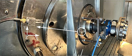
The designed bevel gear meshing tooling is shown in Figures 2 and 3:
1 – Base; 2 – Guide Rail; 3 – Slider; 4 – Mounting Plate; 5 – Pin; 6 – Bracket; 7 – Fixed Block; 8 – Spacer Sleeve; 9 – Support Bolt; 10 – Round Nut; 11 – Spacer Ring; 12 – Cylindrical Self-aligning Roller Bearing; 13 – Cylindrical Thrust Roller Bearing; 14 – Mounting Shaft; 15 – Key; 16 – Bevel Gear
| Component | Function |
|---|---|
| Base | Provides a stable foundation for the tooling. |
| Guide Rail and Slider | Allow the bracket to move along the rail for gear engagement. |
| Mounting Plate | Supports the installation of the gear and related components. |
| Pin | Facilitates the rotation of the fixed block for adjusting the subtended angle. |
| Bracket | Holds the gear and related components in place. |
| Fixed Block | Adjusts the subtended angle by rotating around the pin. |
| Spacer Sleeve | Helps maintain the proper spacing between components. |
| Support Bolt | Used to adjust the position of the fixed block to achieve the desired subtended angle. |
| Round Nut | Prevents the inner and outer rings of the positioning self-aligning roller bearing from loosening. |
| Spacer Ring | Provides additional spacing or adjustment as needed. |
| Cylindrical Self-aligning Roller Bearing and Cylindrical Thrust Roller Bearing | Support the rotation of the mounting shaft and ensure smooth operation. |
| Mounting Shaft | Used to install the bevel gear. |
| Key | Fixes the bevel gear to the mounting shaft to prevent free rotation. |
3. Tooling Operating Steps
(1) Before installing the bevel gear, restore the fixed block to the horizontal state.
(2) Install the bevel gear (No. 16). Note that the inner hole mating surface of the bevel gear needs to be coated with lubricating oil before installation. Additionally, as a detection tooling, here we need to modify the fit size between the outer diameter of the mounting shaft and the inner hole of the bevel gear from the interference or transition fit in the drawing design to a clearance fit, and appropriately reduce the outer diameter of the mounting shaft. These steps all help us install and disassemble the bevel gear smoothly.
(3) Install the key (No. 15) to fix the bevel gear and the mounting shaft and prevent the individual bevel gear from freely rotating around the mounting shaft.
(4) Check the pre-tightening round nut (No. 10) at the tail of the mounting shaft to prevent the assembly loosening of the inner and outer rings of the self-aligning roller bearing used for positioning below the tooling.
(5) According to the subtended angle designed in the gear drawing, adjust the support bolt (No. 9) to drive the fixed block (No. 7) to rotate around the pin (No. 5) to achieve the subtended angle. When the subtended angle is 0°, straight cylindrical gears can be paired for inspection.
(6) Move the bracket (No. 6) along the guide rail to smoothly engage the two bevel gears together.
(7) Lock the locking slider (No. 3) to fix the bracket and prevent the bracket from displacing laterally along the guide rail (2).
(8) Through the hexagonal wrench inner hole at the end face of the mounting shaft (No. 14), the two meshing gears can be easily manually rotated around the shaft for meshing.
4. Main Parameters and Application Range
(1) Overall Dimensions: 2000 mm × 1020 mm × 1300 mm
(2) Application Range of the Tooling: Straight cylindrical gears, straight bevel gears
(3) Adjustable Subtended Angle Range of the Tooling: 0 – 20°
(4) Gear Diameter Range: Ф800 – Ф1200
(5) Maximum Bearing Weight of the Gear: 5 t/piece
| Parameter | Details |
|---|---|
| Overall Dimensions | 2000 mm × 1020 mm × 1300 mm |
| Application Range | Straight cylindrical gears, straight bevel gears |
| Adjustable Subtended Angle Range | 0 – 20° |
| Gear Diameter Range | Ф800 – Ф1200 |
| Maximum Bearing Weight per Gear | 5 t/piece |
5. Meshing Detection Analysis of Straight Bevel Gears
In addition to the tooth profile, the meshing of straight bevel gears is mainly influenced by two parameters: the cone distance and the subtended angle. The cone distance determines the position of the meshing pair of bevel gears on the rotating shaft, similar to the center distance parameter of cylindrical gears. The difference is that the centers of cylindrical gears are parallel to each other, while the centers of bevel gears form a certain angle. The cone distance is a parameter given by the design, and we can adjust the cone distance to achieve the adjustment of the backlash of the meshing tooth surface. Moving towards the small end of the bevel gear, the backlash becomes smaller, and vice versa. However, this only works when the subtended angles of the two bevel gears are consistent. If the subtended angles of the paired bevel gears are inconsistent, the effect of adjusting the tooth surface backlash by adjusting the cone distance will disappear.
The subtended angle is a parameter that reflects the angle between the center of the bevel gear and the straight line of the pitch circle. It directly determines the size of the contact spot area on the tooth surface of the two known bevel gears, thereby determining the quality of power transmission at the meshing surface. Practice shows that there are four situations regarding the subtended angle in the assembly process of bevel gears:
The first is the ideal meshing state of bevel gears, as shown in Figure 4. In this case, the straight lines of the pitch circles of the two bevel gears will overlap, and the tooth surface backlash will be completely eliminated, with both the meshing surface and the non-meshing surface backlash being zero. In practical applications, considering the existence of processing errors and the easy jamming of meshing teeth under zero backlash, this situation is basically not adopted.
| Meshing State | Characteristics |
|---|---|
| Ideal State | The straight lines of the pitch circles of the two bevel gears overlap, and the tooth surface backlash is zero. |
The second is the parallel meshing state of bevel gears, as shown in Figure 5. It refers to the case where the backlash on the meshing surface of the gear is zero before and after, while there is a certain backlash value on the non-meshing surface, and the backlash value at the front and rear positions of the bevel gear along the tooth width direction is equal. The specific backlash value is determined by the designer based on the processing accuracy level of the gear and the operating conditions. If the measured backlash value of the actually paired bevel gears is larger than the designed requirement, it means that the two gears need to move a certain distance inward along the axial direction; conversely, if the measured backlash value is smaller than the designed requirement, the two gears need to move a certain distance outward along the axial position. This distance adjustment is generally achieved by adjusting the width of the two spacer sleeves installed at the front and rear positions of the bevel gear.
| Meshing State | Characteristics |
|---|---|
| Parallel State | The backlash on the meshing surface is zero, and there is a certain backlash on the non-meshing surface with equal values at the front and rear positions along the tooth width direction. |
The third is the meshing state of bevel gears with a larger subtended angle, as shown in Figure 6. In this state, the measured backlash value at the small end of the bevel gear is smaller than that at the large end using a feeler gauge, and the backlash values on the meshing and non-meshing surfaces at the large end are not zero. This indicates that only a part of the tooth surface at the small end of the paired bevel gears can effectively transmit power, which will inevitably lead to intensified wear of the contact tooth surface, greatly reducing the service life of the bevel gears, and irregular meshing abnormal sounds will occur during operation. Once this situation occurs, the bevel gears can only be directly scrapped, or for some cases with small deviations in the backlash value, they can be manually repaired and then used as substandard products for downgraded use.
| Meshing State | Characteristics |
|---|---|
| Larger Subtended Angle State | The backlash at the small end is smaller than that at the large end, and the backlash values on the meshing and non-meshing surfaces at the large end are not zero. |
The fourth is the meshing state of bevel gears with a smaller subtended angle, as shown in Figure 7. This state is just the opposite of the previous one. The measured backlash value at the small end of the bevel gear is larger than that at the large end using a feeler gauge, and the backlash values on the meshing and non-meshing surfaces at the small end are not zero. This indicates that only a part of the tooth surface at the large end of the bevel gears is in normal contact, which will also cause the same problems as shown in Figure 6, and the handling method can also refer to the third case.
| Meshing State | Characteristics |
|---|---|
| Smaller Subtended Angle State | The backlash at the small end is larger than that at the large end, and the backlash values on the meshing and non-meshing surfaces at the small end are not zero. |
6. Conclusion
Gear pairing meshing inspection is very necessary. Its results cannot directly reflect the qualification of a certain individual quality requirement in the gear processing process; it only inspects the assembly quality of the gear meshing. In addition to being directly affected by the tooth profile itself, the meshing detection of bevel gears is mainly influenced by the cone distance and the subtended angle. We can eliminate the tooth profile through single-piece inspection using a tooth profile template; the cone distance is a fixed value given by the design and has no impact on the bevel gear itself once determined; the only remaining determining factor is the subtended angle. The pitch circle is a virtual circle, and it is difficult to measure its specific size in practice, let alone the subtended angle based on the pitch circle. This tooling not only helps us detect the size of the tooth surface backlash of the two bevel gears during meshing before formal assembly but also can calculate and adjust the pitch of the bevel gear according to the actual measured backlash value to achieve an ideal gear meshing state.
In addition to the above content, we also need to consider the anti-dumping investigations launched by Thailand, Brazil, and Türkiye against Chinese tire and rubber products. Recently, these three countries have initiated relevant anti-dumping investigation procedures against Chinese tires and rubber products.
Thailand has launched the second anti-dumping sunset review investigation against motorcycle rubber inner tubes originating from China. On November 14, 2023, the Thai Dumping and Subsidy Review Board issued an announcement stating that it has initiated the second anti-dumping sunset review investigation against motorcycle rubber inner tubes originating from China. The Thai customs code for the involved products is 4013.90.20. The announcement takes effect from the day following its issuance.
In July 2011, Thailand initiated an anti-dumping investigation against the involved products from China. On November 28, 2012, Thailand made a affirmative final anti-dumping ruling, deciding to impose anti-dumping duties ranging from 30.34% to 112.51% on the involved products from China, with a validity period of 5 years. On November 29, 2017, the Foreign Trade Department of the Ministry of Commerce of Thailand initiated the first anti-dumping sunset review investigation against motorcycle rubber inner tubes imported from China. On November 30, 2018, Thailand made the first sunset review final ruling, deciding to continue imposing anti-dumping duties on the involved products from China, maintaining the original duty rate unchanged, with a validity period of 5 years, from November 30, 2018, to November 29, 2023.
Brazil has restarted the evaluation procedure for the anti-dumping case against Chinese truck and bus tires! On December 4, the Foreign Trade Secretariat of the Ministry of Development, Industry, Trade, and Services of Brazil issued Announcement No. 49 of 2023, initiating the evaluation procedure for the scope of application of the anti-dumping duties determined by GECEX Resolution No. 198 of 2021 and GECEX Resolution No. 176 of 2021. The involved products are tires with rim sizes of 20″, 22″, and 22.5″ originating from China, South Korea, Japan, Russia, and Thailand.
The evaluation content is whether to include tire components with rim sizes of 20″, 22″, and 22.5″ under tariff codes 8716.90.90, 8708.70.10, and 8708.70.90, which have the same characteristics as the involved products under tariff code 4011.20.90, within the scope of taxation. The announcement takes effect from the date of its issuance.
Turkey has launched an anti-circumvention investigation into the anti-dumping case of vulcanized rubber conveyor belts involving China. On November 28, 2023, the Ministry of Trade of Turkey issued an announcement stating that, upon the application of a domestic enterprise, it has initiated an anti-circumvention investigation into the anti-dumping case of vulcanized rubber conveyor belts originating from China, India, and Vietnam, to examine whether the Chinese involved products are exported to Turkey via Malaysia to circumvent the anti-dumping duties. The investigation period for this case is the whole year of 2020, the whole year of 2021, the whole year of 2022, and January to September 2023. The involved products are vulcancanized rubber conveyor belts with a trapezoidal cross-section (except for V-shaped grooves), involving Turkish tariff codes 4010.32, 4010.34, and 4010.39.
In 2006, Turkey initiated an anti-dumping investigation against vulcanized rubber conveyor belts originating from China, India, and Vietnam. On March 31, 2007, Turkey began to impose anti-dumping duties of 5.04 US dollars/kg, 3.5 US dollars/kg, and 4.55 US dollars/kg on the involved products from these countries, respectively. On March 20, 2012, Turkey initiated the first sunset review investigation into this case. On March 15, 2013, Turkey made the sunset review final ruling for the first time, extending the anti-dumping duties on the involved products from these countries. On March 2, 2018, Turkey initiated the second sunset review investigation into this case. On October 16, 2018, Turkey made the second sunset review final ruling, continuing to impose anti-dumping duties on vulcanized rubber conveyor belts from China, India, and Vietnam, with a duty amount of 3.15 US dollars/kg for each. On October 7, 2023, Turkey initiated the third sunset review investigation into this case.
These anti-dumping investigations have a significant impact on the trade of related products. It is important for companies to closely monitor the developments of these investigations and take appropriate measures to respond. They may need to engage in legal proceedings, adjust their business strategies, or seek alternative markets to minimize the negative effects.
In conclusion, the design of the meshing detection tool for straight bevel gears is crucial for ensuring the quality and performance of the gears. By accurately measuring and analyzing the meshing parameters, we can identify potential problems and take corrective actions in advance. At the same time, the anti-dumping investigations by different countries also highlight the need for companies to comply with international trade rules and regulations and to enhance their competitiveness through innovation and quality improvement.
Furthermore, in the future, we can expect continued research and development in the field of gear manufacturing and testing to improve the accuracy and reliability of gear meshing. New technologies and materials may be applied to enhance the performance and durability of gears. Additionally, international cooperation and dialogue can play a key role in resolving trade disputes and promoting fair and sustainable trade practices.
Overall, the design and analysis of the meshing detection tool for straight bevel gears, along with the awareness of international trade issues, contribute to the development and progress of the mechanical and manufacturing industries. By continuously improving and optimizing these aspects, we can ensure the efficient and reliable operation of various mechanical systems.