
0 Introduction
Gear transmission has large transmission power, high efficiency, accurate transmission ratio, etc
Advantages, is widely used in mechanical transmission. Meshing in the involute tooth profile
In motion, due to the constant meshing transmission ratio, unchanged meshing angle, and center distance The advantages of divisibility make the involute gear have good meshing characteristics,
And it is relatively easy to manufacture and install . Standard involute straight cylindrical teeth
The design and manufacture of wheels and helical gears have been standardized and applied in mechanical transmission The most extensive. Involute spur cylindrical gear meshing transmission process, two When the tooth surface of the gear teeth is in contact, the load is suddenly added or removed along the full tooth width, so it is so High impact and noise, poor transmission smoothness. Helical cylindrical gear tooth profile The surface is an involute helix surface, and the contact line is inclined when the tooth surfaces of the two wheels are in contact The axis has the advantage that the gear teeth meshing is gradually entering and exiting the meshing, so The meshing transmission has a large bearing capacity, a large degree of overlap, and a stable transmission, but the disadvantages are There are large axial forces during transmission . Therefore, cylindrical teeth on arc teeth The research on wheel meshing transmission has received extensive attention from scholars at home and abroad. arc
The toothed structure of a toothed cylindrical gear is similar to a herringbone gear, so it has
The advantages of herringbone gears, that is, high gear transmission coincident, small axial load,
Strong carrying capacity. At the same time, in the arc tooth cylindrical gear meshing process, each
The meshing and de-out of the gear teeth is carried out gradually, compared to the straight cylindrical teeth Wheels and helical gears, which have neither the meshing impact phenomenon of spur gears, nor the none The axial force of helical gear meshing transmission, so its transmission performance is better .
In addition, since the tooth direction of the arc tooth cylindrical gear is a circular arc tooth line, the arc tooth Cylindrical gears can be rotated at a small angle along the tooth line when mounted Affecting its meshing transmission, the gear pair installation parallelism error adaptability is strong. This paper is based on the study of arc tooth cylindrical gears into basic racks Design and manufacturing method of cylindrical gear with arc tooth.
1 Basic parameters and design calculation of arc tooth cylindrical gear
Typically, the study of arc-toothed cylindrical gears is based on the basic rack of arc-toothed cylindrical gears. Figure 1 is the basic rack of the arc tooth cylindrical gear, p and q are the convex and concave surfaces of the gear teeth, they are part of the two cones P and Q, R is the radius of the cone cone at the index circle, t/2 is the axial spacing of the two cones, b is the width of the rack, A-A section is the middle section of the rack, B-B section is the rack indexing plane, and the rack at section A-A has an involute tooth shape. Studies have found that arc teeth cylindrical gears are in the wheel
The tooth profile of the middle section of the tooth is the same as that of the involute spur cylindrical gear, so the design calculation of the arc tooth cylindrical gear can be carried out with reference to the involute spur cylindrical gear, and its basic geometric parameters are modulus m, number of teeth z, pressure angle α, tooth top height coefficient h*
A and the backlash coefficient c*, the geometric dimension calculation is the same as that of involute spur cylindrical gears, and the calculation formula is shown in Table 1, the design process of arc-toothed cylindrical gears can be carried out with reference to involute spur cylindrical gears, and the design criteria are the same as spur cylindrical gears. In the design process of spur cylindrical gears, because the main form of failure of the gear is the tooth flank
Fatigue pitting and gear tooth fatigue breakage, so according to the different gear transmission applications, the tooth surface contact fatigue strength or tooth root bending fatigue strength design calculation criteria can be selected for design calculation. Therefore, in the design and calculation process of arc cylindrical gear, the gear material, heat treatment method and accuracy can be selected by referring to the design and calculation process of involute spur cylindrical gear
stage, and then determine the corresponding design criteria according to the working conditions, and determine the number of teeth and modulus of the pinion through calculation. Due to the small number of pinion teeth, considering the root cutting problem, the number of pinion teeth should meet zmin≤z1 when selecting; Once the number of teeth of the pinion is determined, the number of teeth of the large gear can be determined according to the gear transmission ratio, that is, z2=iz1; Then, according to the geometric dimension calculation formula in Table 1, the main size of the arc-toothed cylindrical gear is calculated; Finally, the strength of the arc tooth cylindrical gear can be checked.

Figure 1 Basic rack of arc cylindrical gear
2 Cutting teeth of arc tooth cylindrical gear
2.1 Cutting method of arc tooth cylindrical gear
The cutting processing of arc cylindrical gears is different from that of straight cylindrical gears, and the more typical cutting methods at present mainly include rotary cutterhead method and parallel connecting rod method. Because the rotary cutterhead method is efficient and easy to achieve in the tooth cutting process, this method is widely used in arc tooth cylindrical gear cutting processing, and its principle is shown in Figure 2. When cutting arc cylindrical gears by the rotary cutterhead method, the precise paradigm motion relationship between the cutting cutterhead and the gear tooth blank is accurate, that is, the pitch line speed of the gear tooth blank being machined is equal to the linear speed of the cutting cutterhead joint. During the cutting process of the arc gear
In addition to the rotating main movement, the cutting cutterhead also has a cut feed motion along the radial direction of the tooth blank. When using the Fan Cheng method, because only one cogging can be cut each time, the precise indexing of the tooth blank must be controlled after each gear tooth groove, and then the second cogging is cut, and the arc gear can be completed after all the cogging is cut in turn. Theoretically, arc cylindrical gear cogging can be cut out one at a time using a double-edged tool
A complete cogging groove that forms the convex and concave surface of the tooth, but due to the double-sided edge
The tool is cut with a full edge during the tooth cutting process, so the cut when cutting the cogging
The cutting amount is large, the wear of the tool is fast, and the precision of the cut tooth surface is not high, and it is difficult to cut the arc gear that meets the requirements when actually cutting the teeth. Therefore, on the basis of the practice of cutting teeth using double-sided cutting tools, a single-sided cutting tool cutting processing method is proposed, such as arc teeth cylindrical gear cutting tools
Figure 3 shows. In Figure 3, Re and Ri are internal and external single-edged tools, respectively
Cutterhead radius, α1 is the tool pressure angle. Combined with the practical experience of cutting teeth of double-sided cutting tools, in the process of arc gear cogging cutting, the double-sided cutting tool can be used to roughly cut out the cogging, and then the single-sided cutting tool can be used to cut the convex and concave surfaces of the arc tooth cylindrical gear respectively to ensure the accuracy of tooth cutting.
The advantage of using single-sided cutting tools to cut arc teeth, cylindrical gear convex and concave surfaces is that the inner and outer single-sided cutting tools can be designed as tools with equal radii, and the convex and concave surfaces of the cut gear teeth have high accuracy. However, because the convex and concave surfaces need to be cut separately, the problem of tooth blank installation and tool replacement must be considered during the machining process, and once the tool needs to be replaced during the machining process
Disassembling and assembling the tooth blank will inevitably affect the machining accuracy of the gear teeth. To this end, the single-sided double milling processing method of arc tooth cylindrical gear is proposed, and the processing principle is shown in Figure 4, during the cutting process of arc cylindrical gear gear teeth, two stations are designed on the special milling machine to cut the convex and concave surfaces of the gear teeth. In Figure 4, 1 and 4 respectively represent convex and concave single-edged milling tools located in the left and right stations, 2 and 5 respectively represent the machined arc tooth cylindrical gear blanks when milling convex and concave tooth surfaces, and 3 and 6 are convex and concave single-edge milling tools. It can be seen that the tooth cutting processing of arc cylindrical gears requires special CNC tooth milling equipment to complete.

Figure 2 Cutting principle of arc tooth cylindrical gear rotary cutterhead method

Fig. 3 Arc cylindrical gear cutting cutter

Figure 4 Processing principle of single-sided double milling method of arc tooth cylindrical gear
2.2 Equation of tooth surface of arc tooth cylindrical gear cutting tool
In the process of arc tooth cylindrical gear milling, the milling tool adopts a special tool. In order to design and manufacture special gear milling tools, the tooth surface equation of the tooth cutting tool can be studied and built based on the principle of rotary cutterhead method tooth cutting tool. Figure 5 shows the coordinate system of the tool and the gear, first establish the coordinate system [O1, x1, y1, z1] solidly connected to the tooth blank of the machined gear, the coordinate system [Od, xd, yd, zd] and the milling cutterhead are solidly connected, which rotate with the processed gear blank and the milling cutterhead respectively; Then establish a fixed coordinate system [O,x,y,z], [O1,x10,y10,z10] as auxiliary coordinate systems, if the pitch radius of the gear tooth blank is R1 and the average half-diameter of the milling cutterhead is R0, then the inner cutting radius of the milling tool is r0-πm4, and the outer cutting edge radius is r0+πm4. In addition, in Figure 5, ω
and ω1 are the angular velocity of the tool and the tooth blank, and φ1 is the rotation angle of the tooth blank.
It can be seen that in the coordinate system [OD,XD,YD,ZD] that is fixed to the tool, the tool surface parametric equation can be established as follows:

where: u is the distance from the reference point along the tapered busbar on the tool surface
Leave; θ is the angle of the tool holder from the central section of the tooth blank to the end face.

Figure 5 Coordinate system of tool and gear
3 Arc tooth cylindrical gear cutting process and macro programming
Combined with the aforementioned analysis of the tooth cutting process, the arc tooth cylindrical gear can be used The tooth cutting process is carried out in three steps: the first step is the cylindrical gear teeth in the arc teeth Under the knife in the middle of the groove, a three-sided edge cogging milling cutter is used to mill out the cogging and cut off most of it Split billet material; The second and third steps are processed separately with single-sided cutting tools Concave and convex tooth surfaces of arc cylindrical gears. Machining on special milling machines , the indexing of the processing process adopts two methods: absolute and relative If the gear is indexed according to the number of teeth at an angle of δ, the processing program begins The first step of the starting angle starts at δ/2, that is, the knife is lowered from the middle of the gear cogging
roughing cogging; The second step starts from δ=0, and the third step starts from the δ
Start the knife and use two single-sided blade tools to concave and convex respectively
tooth surface processing; When each tool completes the entire cogging of the gear for one week,
After tooth profile machining, the machining of the entire arc tooth cylindrical gear can be completed. composed The cut-in of the tool is carried out according to the involute line, so the cutting trajectory of the tool It is to feed according to the involute line. For example, the basics of machining arc-toothed cylindrical gears The parameters are as follows: modulus m=3 mm, number of teeth z=25, and top height system h* A = 1.0, backlash factor C* = 0.25, a cogging cut The cyclic macro program is as follows:
N10R1=3 /m 模数
N20R2=25 /z齿数
N30R3=R1*R2/2 /d分度圆直径
N40R4=1 /ha齿顶高系数
N50R41=0.25 /齿顶系数
N60R42=0 /变位系数
N70R5=1 /齿根高系数
N80R6=R3/2+R4*R1 /齿顶圆半径
N90R7=R3/2-R4*R1 /齿根圆半径
N100R8=1 /t渐开线开度初始值0~1减量
N110R9=0 /t增量
N120R10=60*R8 /α取值
N130R11=3600/R2 /每齿分度角 3600/R2
N140R12=0 /R12=A 齿 轮 旋 转 角 度 A=R10
-atan((pi*R2*R10/180)/R2)
N150R13=R3*cos(R10)+pi*R3*R10/180 * sin(R10) /
R13=X赋值
N160R14=R6+5 /刀具在 X进给方向上起始位置
N170G90G54G0A0X=R14 /工件快速转动到 A0,刀具快速移
动到离齿顶5mm 处
AA:
N180G01X=R13A0F300 /移动到起始点
N190R8=R8-0.002 /R8赋值
N200R10=60*R8 /α角度取值
N210G01X=R3*cos(R10)+pi*R3*R10/180 * sin(R10)A
=R10-atan((pi*R2*R10/180)/R2)F300/运动点 X,A
N220IFR8>0GOTO AA /循环
N222BB: /BB循环
N230R9=R9-0.002
N240R101=60*R9 /R101 返向回退运动
N250G01X=R3*cos(R101)+pi*R3*R101/180 * sin(R101)
A=R101-atan((pi*R2*R101/180)/R2)F600/反向旋转返回
N260IFR9<1GOTOBB
The arc tooth cylindrical gear milling process is fed in the involute direction, and the retract is also retracted in the involute direction. When the tool moves along the involute direction, pay attention to avoid over-gouging of the unmachined tooth surface, so as to ensure that the surface to be machined has sufficient machining allowance to ensure the arc tooth surface
Processing quality. Figure 6 shows the arc-toothed cylindrical gear obtained by trial cutting, which is tested by meshing transmission to prove that the cut arc-toothed cylindrical gear meets the expected requirements.
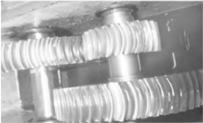
Figure 6 Meshing test of arc tooth cylindrical gear
4 Conclusion
The meshing transmission performance of arc tooth cylindrical gear is better, but because tooth cutting processing requires special processing equipment and milling tools, arc tooth cylindrical gear cannot be widely promoted and applied in mechanical transmission. Based on the research on the design calculation of arc cylindrical gears, this paper focuses on arc cylindrical teeth
The cutting teeth processing of the wheel has been thoroughly studied, and the use of single-sided double milling is proposed
The processing method cuts the convex and concave surfaces of the arc gear teeth and is based on special milling
The tooth equipment is milled. In the process of gear tooth convex and concave milling of arc tooth cylindrical gear, the tool cuts in and exits along the involute trajectory to feed the tool, and after adjusting the machine tool to complete the convex or concave machining of the first gear tooth, the subsequent milling of the gear tooth only requires the precise indexing of the tooth blank, and then repeats the previous cutting feed. Through the preparation of CNC machining macro program, the arc gear is cut on the special gear milling equipment, and the arc tooth circle is cut
The accuracy of column gears is basically 6~7 grades, which has been verified by meshing transmission inspection
The cut arc gear met the expected requirements. Also, if further
To improve the accuracy of arc gears, the tooth surface can be further ground by using a gear grinding machine
Chipping to improve gear accuracy.