0 Preface
Cylindrical gear transmission is a commonly used mechanical transmission method in electric tool products, through cylindrical gear transmission to achieve the purpose of reducing the motor output speed and improving the product output torque, so as to meet the actual use of the product for speed and torque demand. The quality of transmission gears directly affects product quality and the service life of the whole tool, so it is necessary to analyze and improve the manufacturing quality to meet the user’s demand for the life of power tool products. In this paper, the failure mode of cylindrical gear transmission is sorted out and analyzed, and this paper is proposed Corresponding solution.
1 Overview
Cylindrical gears for power tools are mainly driven by small modulus spur teeth or helical gears, which are mainly used for electric stone cutting machines and flashlights
Drill, impact electric drill, jigsaw, electric circular saw and other power tool products, the motor no-load speed is high, the speed ratio is also very large, generally 2.2 ~ 11.25, the output shaft output speed is generally 2 600 r/min ~ 13 800 r/min. For the gear transmission of the first stage reduction, the number of pinion teeth is small, generally 3 ~ 5 teeth, there is a certain degree of root cutting or tooth tip thinning phenomenon in the processing process, the adsorption of grease during gear transmission is poor, and the transmission torque is large, and the transmission is over
The process is more stringent, and it is easy to have gear transmission failure. Therefore, the diagnosis of cylindrical gear transmission failure should be mastered
Failure characteristics, you also need to understand the failure mechanism. From the current market
Feedback and laboratory test results show that cylindrical gears are electric
The two most common gear failure modes in tools include tooth flank fatigue
Plastic deformation, broken or broken teeth caused by labor, etc.
2 Failure mode
2.1 Plastic deformation of tooth surface (fatigue wear)
The plastic deformation caused by tooth surface fatigue is caused by high contact stress and rolling and sliding of the tooth surface in the meshing process of continuous high-speed transmission, which belongs to the failure form of permanent deformation of the tooth, and is at the tooth material under excessive stress It is formed by the plastic flow of the tooth surface or tooth body produced by the yield state. Plastic deformation generally occurs on low-hardness gears, but under heavy loads, high-hardness gears can also occur. This is shown in Figure 1.
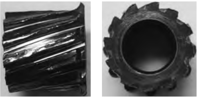
Figure 1 Plastic deformation of tooth surface
During the high-speed transmission of cylindrical gears, there will be a variety of different plastic deformations on the tooth surface with different working conditions.
1) The grease selection of the cylindrical gear transmission process does not match, and the extreme pressure resistance, temperature resistance and adhesion of the grease are poor, thereby losing the lubrication effect that the gear transmission process should have, resulting in dry grinding and heating of the tooth surface, reducing the hardness of the tooth surface and finally leading to plastic deformation of the tooth, that is, biting teeth, and finally shaving phenomenon. This is shown in Figure 2.
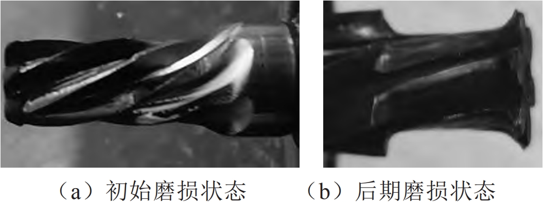
Figure 2 Plastic deformation of tooth surface
2) Due to the excessive backlash of the two tooth surfaces of the cylindrical gear or the excessive mating gap between the inner hole of the gear and the shaft, there is plastic deformation wear caused by mutual or relative sliding friction or impact stress. This is shown in Figure 3.
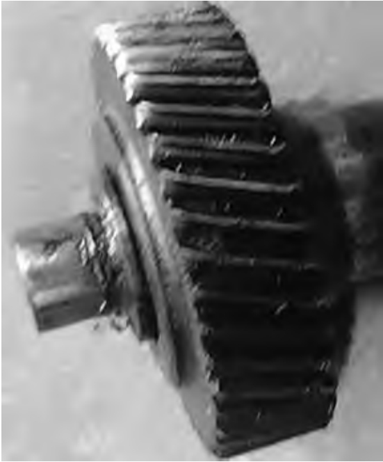
Figure 3 Plastic deformation of tooth surface
3) During the assembly process of cylindrical gears, when abrasive substances (such as sand, iron filings, etc.) fall between the meshing tooth surfaces, the tooth surfaces are gradually worn and scrapped, which is also called abrasive wear.
2.2 Broken teeth
There are many forms of gear tooth breakage, and under normal working conditions, it is mainly the tooth root bending fatigue breakage. When the gear teeth are loaded, at the root of the tooth
The bending stress generated is the largest, coupled with the sudden change in the cross-section of the tooth root transition part and the stress concentration caused by the processing knife marks, when the gear teeth are repeatedly loaded, fatigue cracks will occur at the tooth roots and gradually expand, resulting in fatigue fracture of the gear teeth. This failure mode is common in small analog-to-digital shaft gears. This is shown in Figure 4.

Figure 4 Cylindrical gear teeth broken
In addition, when the teeth are suddenly overloaded or blocked, such as when screwing screws with a first-stage deceleration drill or impact drill, or in progress
Shaft gear overload breakage or shearing may occur during gear locked-rotor experiments, or when the drill bit is momentarily stuck during drilling, or when the reciprocating machinery suddenly fails during the high-speed operation of the jig saw. In addition, after severe wear of the tooth, excessive tooth thickness reduction will also break under normal shock load. Helical cylindrical gear (referred to as helical gear) transmission, wheel
The contact line on the working surface of the tooth is a diagonal line. After the gear teeth are loaded, if the shock load is too concentrated, local breaking occurs. If the shaft bending deformation is too large due to poor manufacturing and installation, and the local load of the gear teeth is too large, even if it is a spur cylindrical gear (referred to as spur gear), local fracture will occur.
3 Solutions
3.1 Tooth surface plastic deformation solution
1) According to the actual working conditions of the gear and the selected materials, reasonably define the hardness of matching cylindrical gears, and the hardness ratio of pinions is larger gears
The hardness is one grade higher, i.e. more than 5 degrees.
2) The use of high viscosity or compound greases containing extreme pressure additives helps to slow down or prevent plastic deformation of the teeth.
3) Reasonable selection of gear backlash, the fit of gear and output shaft can adopt transition fit and interference fit to reduce phase
Friction on sliding or abnormal impact on the tooth surface.
4) The process control should be strengthened for the wear of abrasive particles caused by the meshing tooth surface falling into the abrasive substance during the assembly process of the product.
Ensure clean gear machining tooth surfaces, heat treatment and protection during transfer processes, and the assembly site meets 5S requirements.
3.2 Gear tooth break solution
In order to improve the breaking resistance of the teeth, the following can be taken
Measure:
1) At present, most of the shaft gears such as electric drills, impact drills and jigsaw with one stage deceleration use small module gears with fewer teeth, and the general diameter of the tooth top circle is less than 8 mm, it is recommended to increase the radius of the transition corner of the tooth root and eliminate the processing knife mark to reduce the tooth
Root stress concentration.
2) Increase the rigidity of the shaft and support, that is, the beveled edge transition between the tooth and the bearing gear is adopted to improve the strength of the tail of the shaft gear teeth.
3) Appropriately increase the displacement coefficient of the shaft teeth to increase the thickness of the tooth root and the round diameter of the tooth root, so as to improve the bending strength of the tooth root.
4) For power tools often used in extreme overload or locked-rotor situations, it is recommended to change the shaft tooth material from ordinary medium carbon steel materials such as 40 Cr or 42 CrMo to low-carbon alloy materials such as 20 CrMo or 20 CrMnTi, using carburizing or carbon nitrogen
The heat treatment method of co-osmosis makes the tooth core material have sufficient toughness. Because the shaft gear of medium carbon steel material is easily quenched through the core when performing high-frequency quenching (42 CrMo FM quenching metallographic structure as shown in Figure 6), that is, the tooth surface and core hardness are close, the tooth surface hardness is 54 HRC and the core hardness is 53.5 HRC, tooth
The parts and cores are fine tempered martensitic grade 6, resulting in insufficient core toughness and root fracture under extreme overload conditions.
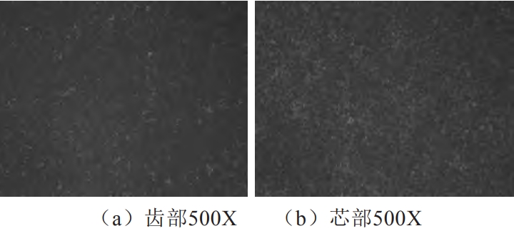
Figure 6 42 CrMo high-frequency quenched metallographic structure
The low carbon alloy material used is subjected to carburizing quenching or carbonitriding heat treatment, the surface hardness of the shaft gear is 58 HRC ~ 62 HRC, the core hardness is 40 HRC ~ 45 HRC, and the related metallographic structure is needle-like martensite and residual austenitic on the surface of the shaft tooth
Body Grade 2 and Fine Granular Carbide Grade 1; The core is low carbon martensitic plus free ferrite grade 1, and its metallographic microstructure characteristics are shown in Figure 7, which can effectively improve the toughness and impact strength of shaft gears.
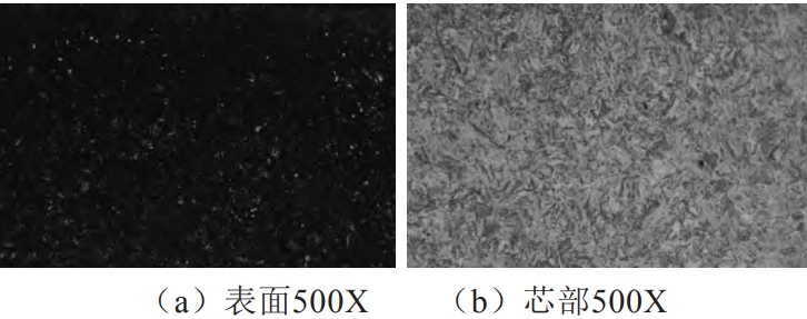
Figure 7 20 Carburized quenched metallographic structure of CrMnTi
4 Conclusion
Cylindrical gear transmission is more commonly used in traditional power tools, and is mainly driven by small modulus straight teeth or helical teeth, due to high speed and harsh use environment, it is easier to cause the failure of transmission gears, such as tooth surface wear, tooth shape failure, transmission accuracy
Reduced, increased clearance and other problems, some noise increases, serious direct tooth chipping or broken teeth. This paper analyzes the two most common cylindrical gear transmission failure modes in power tools, such as plastic deformation caused by tooth surface fatigue and tooth breakage and fracture, and proposes corresponding solutions to provide reference for improving the quality of transmission gears and the service life of products.
