
Arc bevel gear (Gleason system) has the characteristics of high transmission efficiency, compact structure and stable transmission, and is widely used in high-speed and heavy-duty equipment such as automobiles, engineering machinery, aerospace, and ships. Curved tooth cone
Gear strength and dynamic performance are of great significance to ensure the smooth operation of machinery and equipment under complex working conditions and reduce vibration and noise. Compared with other tooth shape structures, the tooth surface of arc bevel gear is more complex, and it is relatively difficult to establish a real finite element model of the tooth surface, and it is difficult to accurately describe the dynamic change mechanism of the actual arc bevel gear pair contact. Therefore, it is very important to establish an accurate finite element model of arc bevel gear and analyze the dynamic performance of tooth surface contact under load conditions. Scholars at home and abroad have done a lot of research on arc bevel gear modeling and contact analysis. Hou Xiangying et al. converted the theoretical calculation formula of the tooth surface into a numerical calculation algorithm, solved the node coordinates and grid unit division of the gear entity according to the finite element theory, and analyzed the contact change of the tooth surface. Litvin described in detail the geometry and meshing principle of arc bevel gears, and explained the theory of using computer simulations and coordinate transformations to shape gear teeth. Yang Bohui et al. accurately calculate the coordinates of the tooth surface mesh nodes through the tooth surface equation, evenly divide the mesh nodes according to the mesh node density requirements, encrypt the tooth root circle transition curve and directly import it into the finite element software to generate an accurate finite element model of arc bevel gear meshing transmission. Wang Yongsheng and others solved the group The parametric equation expressions of each part of the gear size end profile and the tooth line are imported into the software to generate the tooth surface model. Fang Zongde et al. consider the edge contact of the arc bevel gear for the bearing contact point To check the meshing performance of arc bevel gears under working conditions, a geometric analysis method for edge contact is proposed, and the edge contact point is determined, which provides a way for numerical simulation of the whole process of meshing Law. Based on the meshing transmission characteristics of arc bevel gears, Mou Yanming et al. studied the influence of load and speed on the impact of the meshing tooth surface by combining tooth surface contact analysis and bearing contact analysis. In this paper, by analyzing the processing principle of Gleason arc bevel gear, based on the nonlinear equation and meshing principle, the tooth surface equation of the arc bevel gear is obtained through coordinate transformation, the coordinates of each point on the tooth surface are accurately calculated, and a three-dimensional model of the arc bevel gear is established. Using the finite element analysis method, the tooth surface stress and contact imprint changes in the meshing process were obtained, and finally through experimental comparison, it was shown that the proposed method had a certain accuracy.Transmission fit and optimization analysis provide a reliable basis.
1 Modeling of large and small wheel tooth surfaces
1 Equation of the tooth surface of the large wheel
The right-handed wheel is machined by the spreading method [9], and the tooth surface is part of the enveloping surface of the cutting trajectory of the tool. Analyzing the machining process, it can be seen that the cutter disc rotates around the shaft to form the cutting cone, the rocker and the large wheel tooth blank to be machined It is also rotated around the axis to form the tooth surface of the large wheel. To illustrate the large wheel cutterhead position, establish a coordinate system, as shown in Figure 1. In the figure, Om1 is the center of the machine, Og1 is the center of the cutterhead, and the plane of Xg1Og1Yg1 is contained in the plane where the tip is located ( and the machine plane Xm1Om1Ym1 coincide), SR is the axial tooling position, and QR is the angular tooling position.
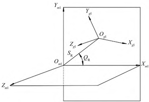
Figure 1 Large wheel cutterhead position
To illustrate the position of the large billet, establish the coordinate system shown in Figure 2. In the figure, Om2 is the design cone vertex of the billet, XB is the bed, X1 is the axial position, and δ1 is the billet mounting angle.
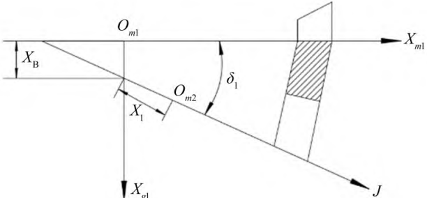
Figure 2 Large wheel billet position
Establish a large wheel cutterhead coordinate system, as shown in Figure 3, rotating around the Zg1 axis in the cutterhead coordinate system to form a cutting cone, Ug and θg are surface coordinate parameters, and α is the tooth angle.
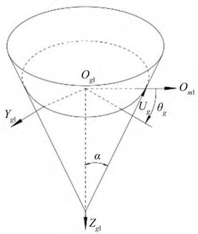
Figure 3 Large wheel cutterhead coordinate system
According to Figure 3, establish the coordinate equation for the cutting cone:
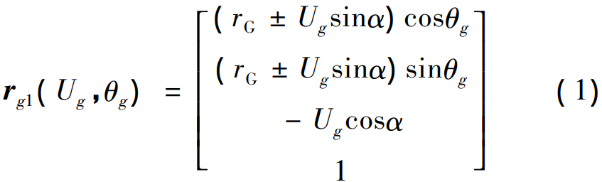
where rg1 is the coordinate equation of the cutting cone; rG is the tip radius (illustrated in Figure 4); “±” indicates the concave and convex surfaces of the machining large wheel, respectively.
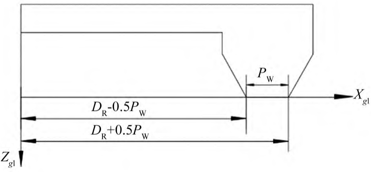
Figure 4 Schematic diagram of the radius of the tip of the tool
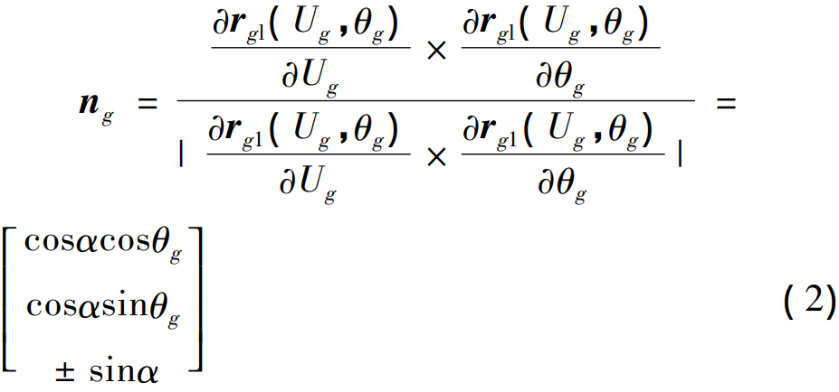
In Figure 4, PW is the tool top distance and DR is the nominal radius of the milling cutterhead. The unit vector ng of the cutting cone of a large wheel can be expressed as:
By the coordinate transformation of equation ( 3), the cutting cone equation can be transformed into the coordinate system solidly connected to the large wheel billet, and the large wheel tooth surface equation r2 ( Ug,θg,φg ) and the normal vector n2 ( Ug,θg,φg ) can be obtained.
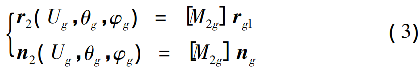
Where: [M2g] is the coordinate transformation matrix; φg is the rocking table corner. Analyzing the machining process of large wheels, it can be seen that there is no expansion motion in the forming method, so φg is zeroed to obtain the tooth surface equation only for θg and Ug
r2 ( θg,Ug ) 。
1.2 Boundary conditions
The surface determined by the tooth surface equation r2 ( θg, Ug ) is a spatial surface with a complex geometry, and the points required to construct the tooth surface of the arc bevel gear must be within the specified range, so the surface coordinates must be defined
The range of quantities θg and φg. Through the projection transformation, it can be seen that the points of the tooth surface of the large wheel must be located in the planar quadrilateral composed of the tooth top line, the tooth root line, the front cone and the back cone surface, as shown in Figure 5.
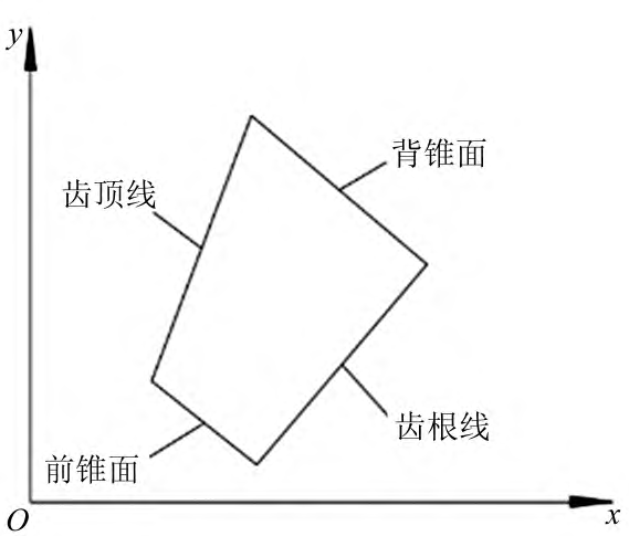
Figure 5 Schematic diagram of the boundary
Calculate the projected point coordinates (x0,y0) of the spatial surface point on the xoy plane:
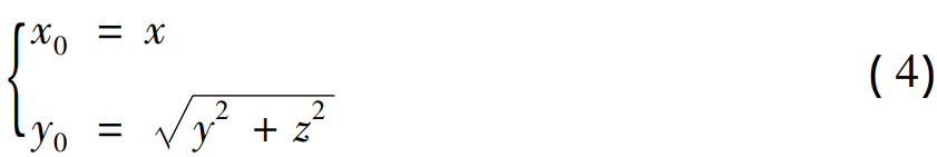
where x is the axial displacement; y is the radial displacement; z is the normal displacement. From this, it is possible to determine whether the point calculated by equation ( 3) meets the boundary conditions, resulting in the range of surface coordinate parameter variables θg and φg. Obviously, the tooth surface equation is a nonlinear equation, and the iterative algorithm is used to call the fsolve function in MATLAB to solve the discrete points of the tooth surface, and the algorithm flow is shown in Figure 6.
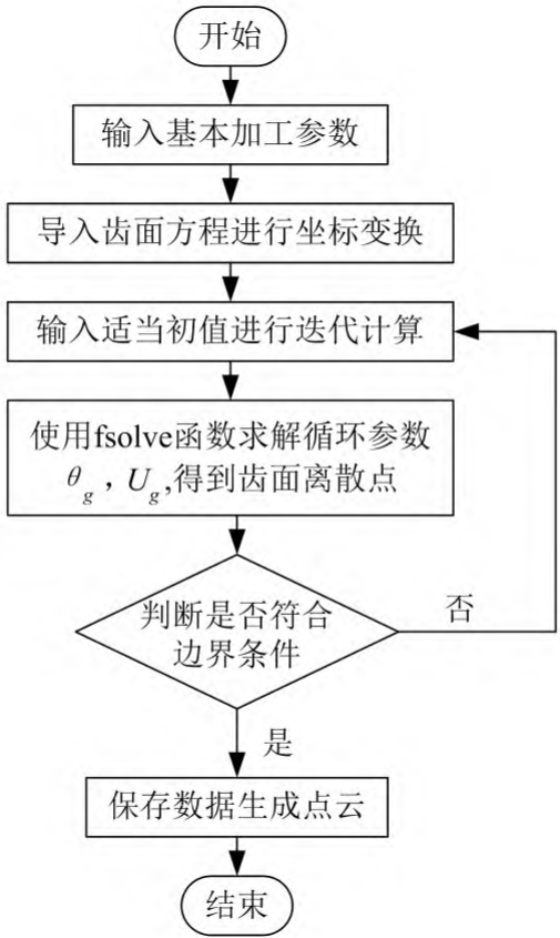
Figure 6 Calculation flowchart
1.3 Tooth surface equation for small wheels
The left-handed wheel is machined by the knife tilt method [13], and the machining principle is basically similar to that of the right-handed wheel, so the modeling process is similar to the above derivation, and the cutterhead position and billet position are shown in Figures 7 and 8. In the figure, Om is the center of the machine tool, Op2 is the center of the cutterhead, and ωc2 is the angular velocity of the rocker.
φc2 is the rocking table angle, and other parameters are defined in accordance with the large wheel.
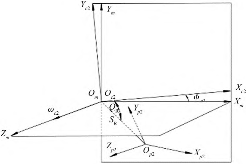
Figure 7 Wheel cutterhead position
The small wheel cutterhead coordinate system is the same as the large wheel cutterhead coordinate system, so it is no longer represented. The tooth surface of the small wheel processed by the knife tilting method is formed by the cutterhead cutting cone bread network, in which the angle of the rocking table is constantly changing and meshing by the contact
The equation shows that the relative velocity v12 of the cutterhead and the billet is perpendicular to the law vector n2, and the relationship is as follows: v12·n2 = 0 ( 5)
Finally, the equation r3 (θg,Ug) of the small gear tooth surface is obtained, and the boundary conditions and solution methods are similar to the principle of the large gear tooth surface.
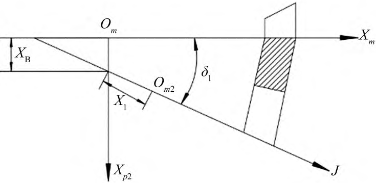
Figure 8 Position of the small wheel billet
2 Modeling of arc bevel gears
The calculation formulas such as the tooth surface equation of the right-handed large wheel and left-handed small wheel analyzed above are written into the corresponding program, and the basic parameters (Table 1) and processing parameters (Table 2) of the arc bevel gear pair are substituted into the program to run.
Table 1 Basic parameters of gear pairs
| parameter | Large wheels | Small wheels |
| 齿数 | 33 | 28 |
| 端面模数/mm | 4.8 | 4.8 |
| 外锥距/mm | 123.3 | 123.3 |
| 齿宽/mm | 37 | 37 |
| 齿顶高/mm | 2.2 | 2.3 |
| 齿根高/mm | 3.3 | 2.9 |
| 节锥角/( °) | 49.4 | 40.2 |
| 根锥角/( °) | 47.5 | 39.3 |
| 面锥角/( °) | 52.5 | 43.1 |
Table 2 Machining parameters
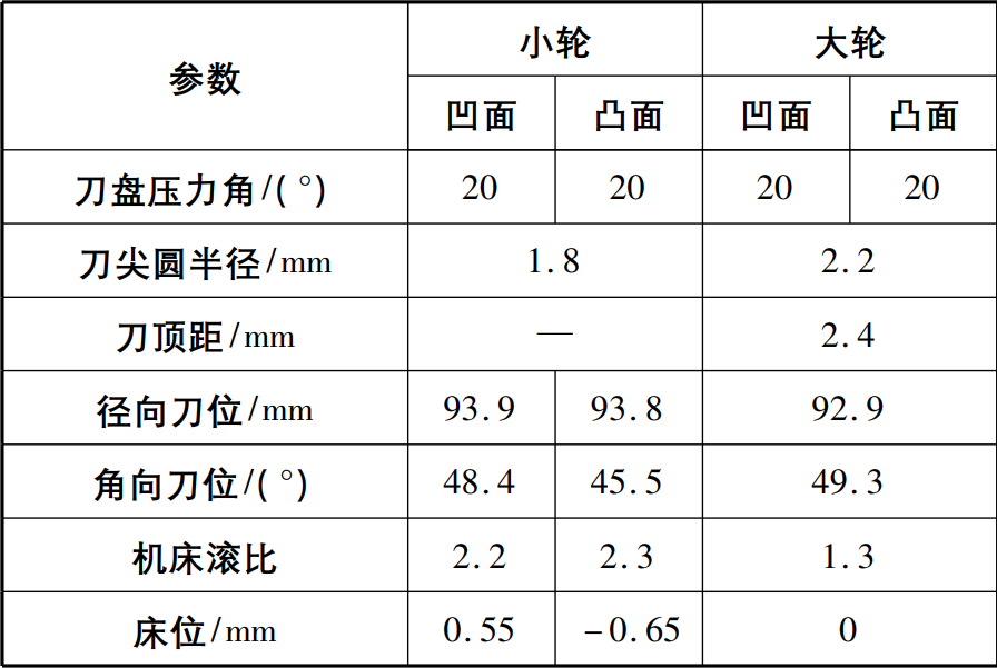
1) According to the formula (3), the large wheel convex and concave are calculated
Discrete points, as shown in Figure 9.
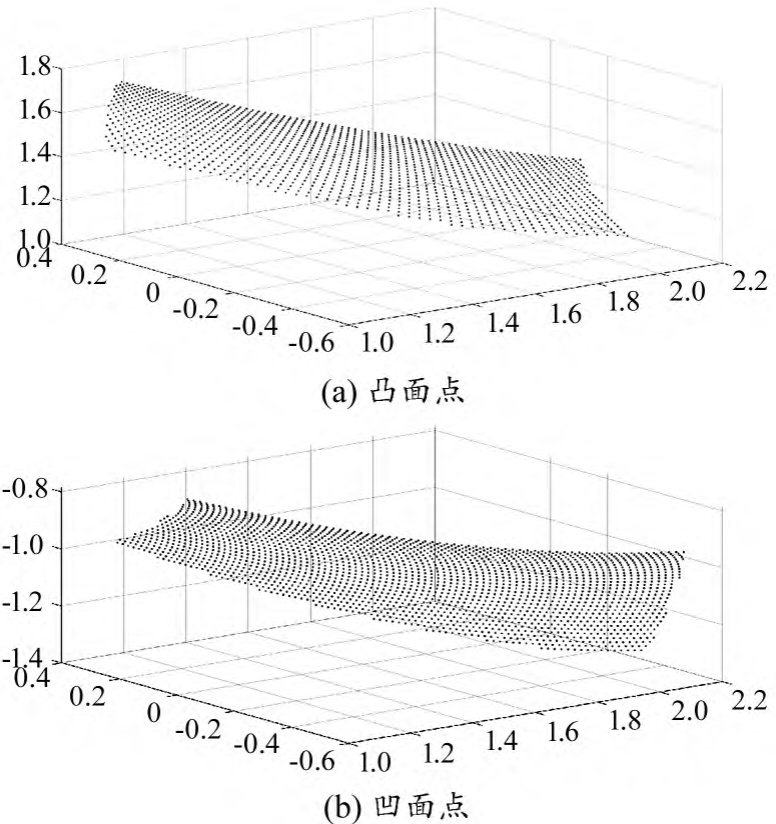
Figure 9 Discrete points of the tooth surface of the large wheel
2) Import the obtained discrete point data into the 3D modeling software SolidWorks in text format, use the obtained point cloud for 3D modeling, and use commands such as curved surface to complete the modeling, as shown in Figure 10
Show. The discrete points are placed in the same coordinate system to generate the concave and convex surfaces of the large wheel, and the shape of the large wheel tooth profile can be generated by using the surface cutting and shearing intersecting surface, and the three-dimensional model of the arc bevel gear large wheel can be established by the array tooth profile.
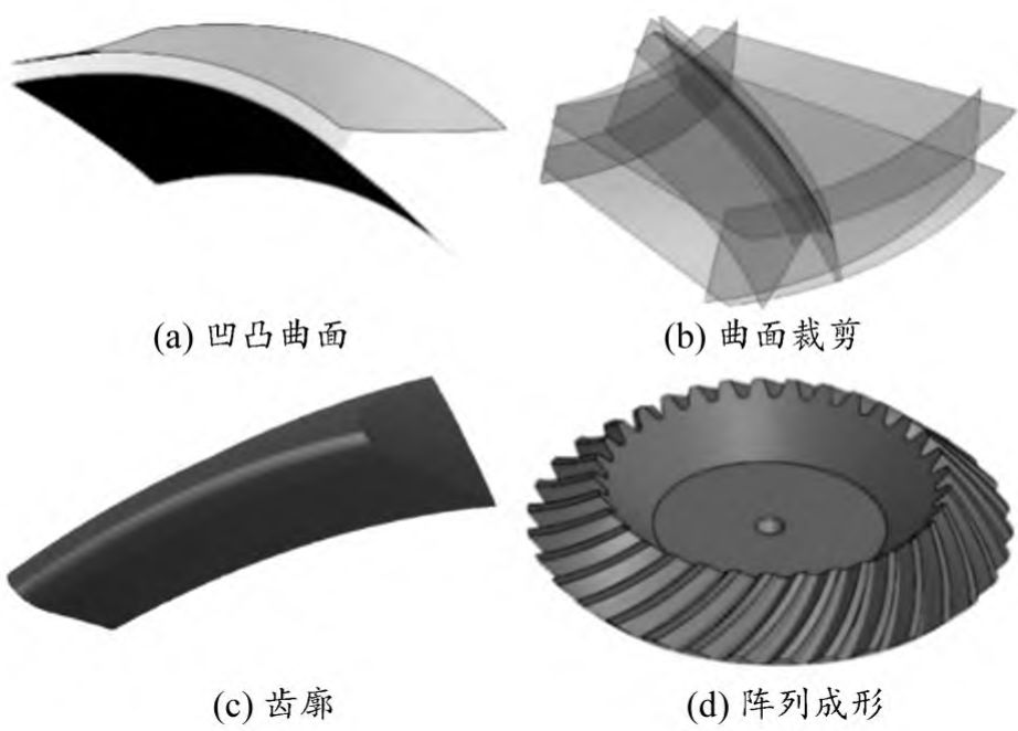
Figure 10 3D model of the large wheel
3) In the same way, establish a three-dimensional model of the small wheel, assemble the gear pair according to the specified position and assemble it with the gear matching command in the mechanical fit, and use the interference check function in the SolidWorks software to visually and clearly observe whether the arc bevel gear assembly is reasonable, avoid interference, and provide good matching conditions for the next finite element dynamic contact analysis.
3 Finite element contact analysis of arc bevel gear
3.1 Establish the finite element analysis model
Based on the finite element software ANSYS Workbench platform, the transient dynamics module is used to perform dynamic contact analysis of arc bevel gears, and the main links include setting model material parameters, meshing, and setting Determine boundary conditions and contact relationships, set solution parameters. Transient dynamics aims to analyze the dynamic response of a structure under transient or steady-state loading, and its output is the response of the contact region over time Force, strain and displacement, etc. Nonlinear transient dynamics is used to analyze the contact process of arc bevel gears, and the commonly used contact analysis algorithm is the augmented Lagrangian method, which can reduce the penetration of contact pressure calculation to an acceptable level.
1) Set the model material parameters.
Import the assembled model into the limited element software Workbench according to the actual arc bevel gear material 18Cr2Ni4WA The specified material parameters are E = 202 GPa and Poisson’s ratio μ = 0. 273, density ρ = 7. 91 g /cm3。
2) Divide the grid.
The accuracy and type of meshing directly determine the accuracy of the 3D model analysis results, and too dense meshes will increase the calculation time and occupy large computer resources. In order to obtain accurate calculation results and improve computational efficiency, the tetrahedral meshing model is selected, and the gear contact surface that is expected to mesh is partially refined, with a mesh size of 1 mm for the refinement part and a mesh size for the non-refined part At 10 mm, the FE mesh model is shown in Figure 11 with a total of 619 607 nodes and 418 275 elements.
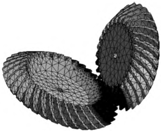
Figure 11 Finite element mesh model of arc bevel gear
3) Set boundary conditions and contact relationships.
During the operation of the arc bevel gear pair, the motor applies torque to the active wheel rotating around the central axis through the wheel shaft, and the active wheel and the driven wheel mesh to drive the driven wheel to rotate around the central axis, and the driven wheel not only loses
The incoming torque is also loaded. Therefore, the applied load is rotated by the active wheel around the central axis at a speed of 600 r/min, and the resistance moments of the driven wheel are 30 N·m and 500 N·m respectively in order to compare the effect of the load on the contact area.
The locally refined tooth surface is selected as the contact area, the large wheel is set as Contact and the small wheel is Target, and the contact algorithm selects the augmented Lagrangian method. Considering that the contact area is a type with friction, the friction coefficient is selected as 0 under normal working conditions0.2。
4) Solution settings.
The parameter setting in transient dynamics contact analysis is more important, in which the parameter setting of the load step determines whether the nonlinear solution is carried out smoothly, and the total time of the load step is set after analysis and testing 012 5 s, starting load substep 50, minimum load substep 20, maximum Large load substep 3 000, opens the large deformation option, and uses iterative algorithms to solve nonlinear contacts transiently.
3.2 Analysis of simulation results and comparison of experiments
Using the simulation results of the finite element model, the elastic deformation of the teeth during the meshing process is obtained, and the contact area becomes larger with the increase of the load, but the overall contact trend will not change due to the change of the load Change. The contact area is distributed at the small end of the middle of the tooth surface and is jujube nucleus-shaped, at a certain angle to the direction of the tooth surface, and the length of the contact area is about 47% of the tooth length and the height is about the height of the full tooth after the cell grid calculation of 60%. The simulation results are basically consistent with the design results, indicating that the established model is accurate and reliable. In order to further verify the correctness of the model and simulation results, the ground arc bevel gear is actually mating experiments. A 500 mm universal rolling checker, as shown in Figure 13, is used due to versatility The rolling checker is used to check the overall contact mark distribution in the contact area, and the appropriate load can be used to achieve the purpose of the experiment, so the load is set to 30 N·m. Adjust the installation position of the arc tooth bevel gear pair by tooth surface coloring, make it fit normally, start the machine, wait for the gear tooth surface to mesh normally, move for a certain period of time, observe the tooth surface contact, obtain the distribution value of the stress of the concave contact surface of the large wheel, and obtain the contact imprint area. According to the actual working conditions, the arc bevel gear is generally meshed at the same time when two or more pairs of gear teeth are engaged, in order to facilitate the observation of the change of stress area, the simulation results of one of the pairs of gear tooth surfaces at 30 N·m and 500 N·m two different loads are explained. Active wheel timing The needle rotates, takes the start, middle and exit three state moments, and obtains the stress distribution in the instantaneous contact zone of the working concave surface, and the tooth surface stress cloud is shown in Figure 12. As can be seen from Figure 12, as the arc bevel gear pair turns, the tooth surface contact area moves along the small end of the tooth to the large end. Due to the tooth surface imprint, this is shown in Figure 14. Analyzing the contact imprints in Figure 12 and Figure 14, it is found that the finite element simulation is basically consistent with the experimental results, which verifies the accuracy of the established model and the finite element contact analysis results. The contact imprints obtained through simulation and experiments are in line with the distribution range of contact areas in the design guidelines, indicating that the designed and manufactured arc bevel gears can meet the actual use requirements.

Figure 12 Tooth surface stress cloud

Figure 13 Universal Scroll Checker
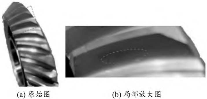
Figure 14 Concave contact impressions
4 Concluding remarks
In this paper, the discrete points of the tooth surface are solved from the principle of arc bevel gear forming, and the three-dimensional model is established through the tooth surface point cloud, which improves the modeling accuracy. The finite element model was established using the Transient Dynamics Module in ANSYS Workbench to extract the concave surface of the arc bevel gear large wheel during meshing After analysis, the simulation results were found to be accurate and reliable. The contact imprints obtained through simulation and experiments meet the requirements of the contact area in the design guidelines, indicating the designed and manufactured arc teeth Bevel gears can meet the actual use requirements.