
I present a comprehensive methodology for the precise design of skiving tools dedicated to orthogonal spur face gears. The face gear drive, formed by a face gear meshing with a cylindrical pinion, has attracted considerable attention in automotive and aerospace industries because of its large contact ratio, compact volume, low mass, and high torque capacity. Nevertheless, its manufacturing accuracy remains a bottleneck. Among the available processes, gear skiving, also called power skiving, combines the advantages of shaping and hobbing, offering a material removal rate typically four to four point two times higher than shaping while maintaining accuracy up to grade seven. The tool structure is far simpler than that of a hob, and existing machine tools can be reused, which substantially reduces cost. The principal drawback of skiving is the inherent principle error that limits its accuracy. My objective is to eliminate this error for the orthogonal spur face gear by designing the skiving tool so that its cutting edge generates the exact conjugate tooth surface.
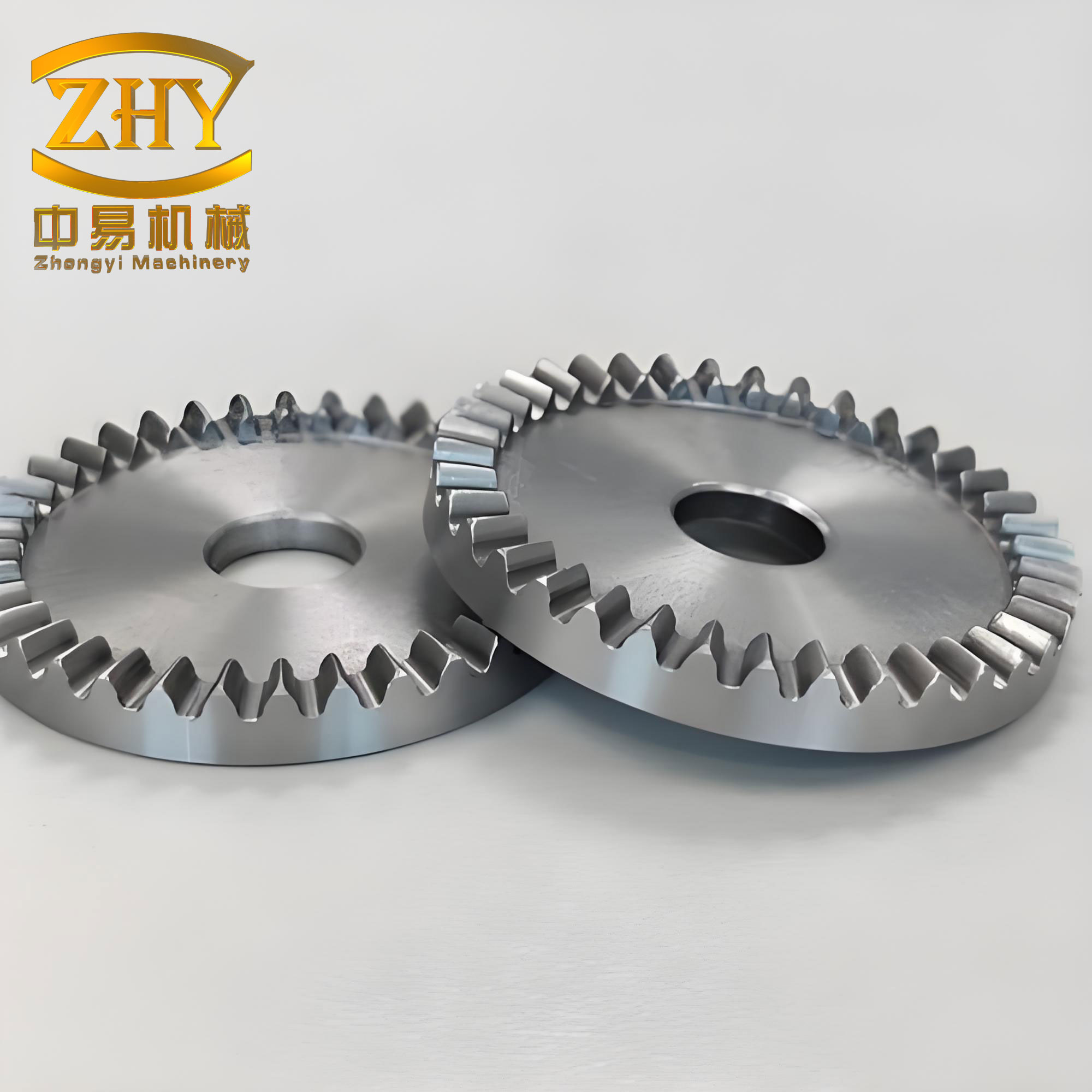
The face gear transmission is a special crossed-axis gear pair. Because the orthogonal spur face gear carries no axial force, it is particularly suitable for skiving. In this article, I treat the skiving process as a two-degree-of-freedom meshing motion between the tool and the face gear blank. The cutting edge of the tool is derived by enveloping the involute profile of the cylindrical pinion that meshes with the face gear. This approach avoids the classical principle error and provides a theoretical basis for high-precision manufacturing of face gears.
I organize the remaining content as follows. First, I analyze the kinematics of the skiving process for the face gear. Then I derive the tool tooth surface by enveloping the pinion tooth profile. Next I construct the normal section, design the tool structure, and obtain the cutting edge expression. After that I solve the meshing condition between the cutting edge and the face gear, deduce the CNC machining law, and compute the theoretical tooth surface numerically. Finally I compare the simulated tooth surface with the theoretical surface and verify the accuracy of the proposed design.
Kinematics of the Skiving Process for the Face Gear
I model the skiving process as a meshing motion of a crossed-axis gear pair. The tool and the face gear blank are forced to mesh, and the excess material is removed by the cutting motion. The cutting speed depends on the rotational speeds of the tool and the face gear as well as the shaft angle. Let me denote the tangential linear velocity of the tool by $v_v$, the linear velocity of the face gear by $v_g$, the component of $v_v$ along the face gear helix by $v_{va}$, and the component along the tooth tangent by $v_{vt}$. The feed velocity of the tool along the face gear helix is $v_{01}$. The cutting speed $v$ is determined by the resultant velocity of the face gear velocity and the tool tangential velocity, together with the helix component.
The angular velocity relation between the tool and the face gear is written as
$$\omega_v = \frac{z_2 \omega_2}{z_v} + \frac{2 v_{01} \sin\beta_2}{m_n z_v}$$
If the face gear provides the incremental motion instead, then
$$\omega_2 = \frac{z_v \omega_v}{z_2} – \frac{2 v_{01} \sin\beta_2}{m_n z_2}$$
where $\omega_v$ is the tool angular velocity, $z_v$ is the number of tool teeth, $\omega_2$ is the face gear angular velocity, $z_2$ is the number of face gear teeth, $m_n$ is the normal module of the face gear, and $\beta_2$ is the face gear helix angle.
Because of the helix angle, the tool axis and the face gear plane axis form a shaft angle $\varepsilon$. This angle is determined jointly by the tool helix angle and the face gear helix angle:
$$\varepsilon = |\beta_v \pm \beta_2|$$
where $\beta_v$ is the tool helix angle. If the tool helix and the face gear helix rotate in opposite directions, the plus sign is used; otherwise the minus sign is used. For an orthogonal spur face gear, the face gear helix angle vanishes, so $\varepsilon = \beta_v$.
The principal kinematic quantities of the face gear skiving process are summarized in Table 1.
| Symbol | Description | Role in the process |
|---|---|---|
| $\omega_v$ | Tool angular velocity | Drives the cutting motion |
| $\omega_2$ | Face gear angular velocity | Provides the generating motion |
| $z_v$ | Number of tool teeth | Sets the transmission ratio |
| $z_2$ | Number of face gear teeth | Sets the transmission ratio |
| $m_n$ | Normal module | Scales the tooth geometry |
| $\beta_2$ | Face gear helix angle | Zero for the orthogonal spur face gear |
| $\beta_v$ | Tool helix angle | Equals the shaft angle for the orthogonal spur face gear |
| $v_{01}$ | Feed velocity along the face gear helix | Generates the tooth width |
| $\varepsilon$ | Shaft angle | Controls the crossed-axis configuration |
Tool Design Based on the Pinion Tooth Surface
My design strategy is to envelope the skiving tool tooth surface from the involute profile of the cylindrical pinion that meshes with the face gear. Let the pinion, the tool, and the face gear be arranged so that the pinion and the tool share the same pitch circle tangent condition. I denote the pitch radius of the pinion by $r_{p1}$, the pitch radius of the tool by $r_{pv}$, and the center distance between the pinion and the tool by $t$. The pinion and the tool rotate about parallel axes, while the face gear rotates about an axis perpendicular to the pinion axis.
Pinion Tooth Surface Equation
I express the pinion tooth surface in the coordinate system $S_1$ as
$$R_1(u_1,\theta_1) = \begin{bmatrix} r_{b1}[\sin(\theta_1+\theta_{o1}) – \theta_1\cos(\theta_1+\theta_{o1})] \\ -r_{b1}[\cos(\theta_1+\theta_{o1}) + \theta_1\sin(\theta_1+\theta_{o1})] \\ u_1 \end{bmatrix}$$
where $r_{b1}$ is the base circle radius of the pinion, $r_{b1} = m_n z_1 \cos\alpha / 2$, $z_1$ is the number of pinion teeth, $\alpha$ is the pressure angle at the pitch circle, $\theta_1$ is the involute roll angle parameter, $\theta_{o1}$ is the half tooth space angle at the base circle, and $u_1$ is the tooth width parameter.
The normal vector of the pinion tooth surface in $S_1$ is
$$n_1(u_1,\theta_1) = -\begin{bmatrix} \cos(\theta_1+\theta_{o1}) \\ \sin(\theta_1+\theta_{o1}) \\ 0 \end{bmatrix}$$
The pinion tooth profile is the starting point for the entire design. Because the pinion is the conjugate mate of the face gear, enveloping its profile yields a tool that can reproduce the correct face gear tooth surface.
Tool Tooth Surface by Enveloping
I establish the coordinate systems for the pinion enveloping the skiving tool. Let $S_1$ and $S_a$ be the pinion moving and fixed coordinate systems, $S_v$ and $S_0$ be the tool moving and fixed coordinate systems, and $S_b$ be an auxiliary coordinate system. The center distance is $t_1$. The pinion feeds along its own axis in the reverse direction with velocity $v_0$ over a feed distance $l$. The tool rotates about the $z_v$ axis by angle $\varphi_v$, and the pinion rotates about the $z_1$ axis by angle $\varphi_1$.
During enveloping, the angular velocities satisfy
$$\omega_1 = \frac{z_1 \omega_v}{z_v} – \frac{v_0}{p}$$
where $z_1$ and $z_v$ are the pinion and tool tooth numbers, $\omega_1$ and $\omega_v$ are the pinion and tool angular velocities, $v_0$ is the axial feed velocity of the pinion, and $p$ is the helix parameter defined by
$$p = \frac{m_n z_v \sin\beta_v}{2 \cos\beta_v}$$
The tool angular velocity therefore consists of the rolling component and an additional component caused by the axial feed of the pinion. Using coordinate transformation, the tool tooth surface and its normal vector are
$$R_v(u_1,\theta_1,\varphi_1,l) = M_{v1}(\varphi_1,l) R_1(u_1,\theta_1)$$
$$n_v(u_1,\theta_1,\varphi_1,l) = L_{v1}(\varphi_1,l) n_1(u_1,\theta_1)$$
with the transformation matrix
$$M_{v1} = M_{v0} M_{0b} M_{ba} M_{a1}$$
Here $M_{ij}$ with $i = a,b,0,v$ and $j = 1,a,b,0$ denotes the transformation from coordinate system $S_j$ to $S_i$, and $L_{ij}$ is the upper-left $3\times 3$ submatrix of $M_{ij}$.
Because the pinion rotation and the axial feed are two independent meshing parameters during enveloping, the meshing conditions between the pinion and the tool are
$$f_1 = n_v \cdot \frac{\partial R_v}{\partial \varphi_1} = 0$$
$$f_2 = n_v \cdot \frac{\partial R_v}{\partial l} = 0$$
Solving these equations yields the tool tooth surface. I define the angle between the tooth surface and the tooth width direction as the helix angle $\beta_v$. This surface is the envelope of the pinion tooth profiles and therefore contains the conjugate information of the face gear.
Cutting Edge of the Skiving Tool
To give the tool cutting capability, I introduce a rake angle $\eta$ and a working relief angle $\Delta\beta$. I construct a normal plane perpendicular to the tool tooth surface. This plane is rotated about the top edge by the rake angle $\eta$ to become an auxiliary plane. The intersection curve between the auxiliary plane and the tooth surface is the cutting edge. To keep the tool tooth surface unchanged while making the rake face a concave quasi-prism along the tool helix, a small-diameter milling cutter can be used. The relief face is a continuous negative modification surface so that the left and right flanks possess the working relief angle $\Delta\beta$.
The auxiliary plane equation is
$$y_v \tan\eta \left(x_v \sin\beta_v – z_v \cos\beta_v\right) = 0$$
Combining this with the tool tooth surface equation yields the cutting edge $R_c$:
$$R_c = \begin{cases} R_v = M_{v1} R_1 \\ R_v^{(2)} \tan\eta \left[ R_v^{(1)} \sin\beta_v – R_v^{(3)} \cos\beta_v \right] = 0 \\ n_v \cdot \frac{\partial R_v}{\partial \varphi_1} = 0 \\ n_v \cdot \frac{\partial R_v}{\partial l} = 0 \end{cases}$$
The structural parameters of the tool are collected in Table 2. The rake angle and the relief angle determine the cutting performance, while the helix angle and the number of teeth determine the generating motion.
| Parameter | Symbol | Function |
|---|---|---|
| Number of tool teeth | $z_v$ | Sets the transmission ratio with the face gear |
| Tool helix angle | $\beta_v$ | Equals the shaft angle for the orthogonal spur face gear |
| Rake angle | $\eta$ | Controls the cutting edge location |
| Relief angle | $\Delta\beta$ | Provides cutting clearance |
| Normal module | $m_n$ | Scales the tool tooth |
| Pressure angle | $\alpha$ | Defines the involute profile |
Derivation of the Face Gear Tooth Surface
After obtaining the cutting edge, I use it to generate the pinion tooth profile and then to machine the face gear. The process is divided into two stages. In the first stage, the cutting edge generates the pinion tooth profile. In the second stage, the pinion and the face gear mesh with a fixed transmission ratio, and the tool feeds along the face gear helix to machine the entire tooth width.
Generation of the Pinion Profile by the Cutting Edge
I establish the coordinate system in which the cutting edge generates the pinion profile. The cutting edge $R_c$ rotates about the $z_c$ axis by angle $\varphi_v$, and the pinion rotates about the $z_1$ axis by angle $\varphi_1$. The coordinate systems $S_c$ and $S_f$ are the cutting edge moving and fixed systems. The cutting edge meshes with the pinion rotationally and simultaneously feeds along the pinion axis with velocity $v_1$, thereby generating the pinion profile.
The simulation of the pinion profile generated by the cutting edge shows that both the left and right flanks exhibit a small residual error, with a maximum of about two point two micrometers. This residual arises from model conversion and the numerical interpolation tolerance of the simulation software. The error is small enough to confirm that the cutting edge can envelope the pinion profile and that the proposed cutting edge design is accurate.
Coordinate System for Face Gear Skiving
During face gear skiving, the tool generates the involute end section of the pinion while simulating the meshing between the pinion and the face gear, and it feeds along the face gear helix to complete the entire face gear tooth surface. I establish the coordinate system for face gear skiving. The cutting edge $R_c$ rotates about the $z_f$ axis by angle $\varphi_v$, the face gear rotates about the $z_2$ axis by angle $\varphi_2$, and $\gamma$ is the angle between the tool axis and the face gear central axis. The center distance at the initial position is $L_0$. The coordinate systems $S_f$ and $S_p$ are the absolute systems of the tool and the face gear at the initial position, while $S_c$ and $S_2$ are rigidly connected to the tool and the face gear, respectively. $S_m$ is an auxiliary system.
The tool rotates about the $z_f$ axis with angular velocity $\omega_v$, and the face gear rotates about the $z_p$ axis with angular velocity $\omega_2$. The tool feeds along the negative $z_m$ direction with velocity $v_{01}$, so the machined tooth width is
$$S = \left\| v_{01} \cdot \frac{\varphi_2}{\omega_2} \right\| = \left\| v_{01} \cdot \frac{\varphi_v}{\omega_v} \right\|$$
The rotation relation between the tool and the face gear is
$$\varphi_2 = \frac{\varphi_v z_v}{z_2} = i_t \varphi_v$$
where $\varphi_2$ and $\varphi_v$ are the rotation angles of the face gear and the cutting edge relative to the initial position, and $i_t$ is the transmission ratio between the tool and the face gear. The coordinate transformation from the tool fixed system to the face gear moving system is
$$M_{2f} = M_{2p} M_{pm} M_{mf}$$
The cutting edge equation in the face gear moving coordinate system is
$$R_2 = M_{2f}(S) M_{fv}[\varphi_v(\varphi_1)] R_c$$
Meshing Equation and Face Gear Tooth Surface
The face gear tooth surface is generated by two families of contact lines during enveloping. One family corresponds to constant $S$ with $\varphi_v$ as a variable, and the other corresponds to constant $\varphi_v$ with $S$ as a variable. The instantaneous contact point $q$ between the tool and the face gear tooth surface is the intersection of the two contact lines.
The normal vector of the face gear tooth surface is
$$n_2 = \left( \frac{\partial R_2}{\partial u_1} + \frac{\partial R_2}{\partial \theta_1} \frac{\partial \theta_1}{\partial u_1} \right) \times \left( \frac{\partial R_2}{\partial \varphi_1} + \frac{\partial R_2}{\partial \theta_1} \frac{\partial \theta_1}{\partial \varphi_1} \right)$$
The meshing conditions related to the two parameters are
$$n_2 \cdot \frac{\partial R_2}{\partial \varphi_v} = 0$$
$$n_2 \cdot \frac{\partial R_2}{\partial S} = 0$$
Combining these with the cutting edge equation gives the face gear tooth surface equation:
$$\begin{cases} R_2 = M_{2f}(S) M_{fv}[\varphi_v(\varphi_1)] R_c \\ n_2 \cdot \frac{\partial R_2}{\partial \varphi_v} = 0 \\ n_2 \cdot \frac{\partial R_2}{\partial S} = 0 \end{cases}$$
Because the cutting edge and the face gear tooth surface are in point contact, while the pinion and the face gear are in line contact, I set the pinion rotation angle $\varphi_s$ to zero when the pinion meshes with the face gear. At this instant, I obtain the contact line between the pinion and the face gear. I discretize this contact line uniformly along the face gear tooth width from the outer radius to the inner radius into thirteen points $a_k$ with $k = 1,2,\ldots,13$. For each discrete point, I compute the corresponding tooth height and tooth width in the face gear rotational projection plane:
$$\begin{cases} R_{2a_k}^{(3)} = H_k \\ \left(R_{2a_k}^{(1)}\right)^2 + \left(R_{2a_k}^{(2)}\right)^2 = L_k \end{cases}$$
where $R_{2a_k}^{(1)}$, $R_{2a_k}^{(2)}$, and $R_{2a_k}^{(3)}$ are the coordinates of the contact point along the $x$, $y$, and $z$ axes of the face gear coordinate system, and $H_k$ and $L_k$ are the tooth height and tooth width of the contact point.
Substituting the tooth height and tooth width of the contact line into the face gear tooth surface equation yields the face gear tooth surface coordinates at the contact points:
$$\begin{cases} R_k^{(3)} = H_k \\ \left(R_k^{(1)}\right)^2 + \left(R_k^{(2)}\right)^2 = L_k \\ n_2 \cdot \frac{\partial R_k}{\partial \varphi_v} = 0 \\ n_2 \cdot \frac{\partial R_k}{\partial S} = 0 \end{cases}$$
From this system, I obtain the motion parameters of the cutting edge at the discrete points, namely the helix feed distance $S$ and the tool rotation angle $\varphi_v$. The error between the theoretical face gear tooth surface meshing with the pinion and the skived face gear tooth surface at the contact point is
$$\delta_k = \left[ R_{2a_k} – R_k \right] \cdot n_2$$
The numerical results show that the error at the contact points is extremely small. This demonstrates that the contact point between the cutting edge and the face gear can lie on the contact line between the pinion and the face gear during skiving.
Numerical Modeling and Simulation of Face Gear Skiving
To verify the accuracy of the tool design and the face gear tooth surface calculation, I build a numerical model of the face gear. The parameters used in the model are listed in Table 3.
| Parameter | Symbol | Value |
|---|---|---|
| Number of pinion teeth | $z_1$ | 30 |
| Number of tool teeth | $z_v$ | 27 |
| Number of face gear teeth | $z_2$ | 150 |
| Tool helix angle | $\beta_v$ | $7^\circ$ |
| Shaft angle | $\gamma$ | $90^\circ$ |
| Shaft angle | $\varepsilon$ | $7^\circ$ |
| Normal module | $m_n$ | 3.0 mm |
| Pressure angle | $\alpha$ | $25^\circ$ |
| Relief angle | $\Delta\beta$ | $5^\circ$ |
| Inner radius | $l_1$ | 224 mm |
| Outer radius | $l_2$ | 249 mm |
Using these parameters, I obtain the numerical model of the face gear produced by skiving. A comparison with the standard face gear tooth surface shows that the tool designed by this method produces no theoretical error when machining the face gear. This is a direct consequence of the fact that the tool tooth surface is the envelope of the pinion profile, and the pinion is the conjugate mate of the face gear.
CNC Machine Tool Configuration and Machining Law
The six-axis CNC skiving machine tool includes five numerically controlled motion axes: three translational axes $X$, $Y$, and $Z$, and two rotational axes, namely the tool rotation axis $C$ and the face gear rotation axis $B$. The $X$, $Y$, and $Z$ axes control the spatial position of the tool and the feed motion along the face gear helix. The $C$ and $B$ axes control the rotation of the tool and the face gear, respectively. The $A$ axis adjusts the shaft angle between the tool axis and the face gear helix.
I establish the machine tool motion coordinate system according to the machine structure. The coordinate systems $S_a$ and $S_c$ are the machine fixed and moving systems of the cutting edge, and $z_a$ is the tool rotation axis rigidly connected to the machine spindle. The coordinate systems $S_h$ and $S_2$ are the machine fixed and moving systems of the face gear, and $z_2$ is the face gear rotation axis rigidly connected to the $B$ rotation axis. The coordinate transformation from $S_a$ to $S_2$ is
$$M_{c2a} = M_{2h} M_{hb} M_{ba}$$
I select the origin of the face gear fixed coordinate system as the zero point of the NC program. The quantities $C_X$, $C_Y$, and $C_Z$ denote the travel distances of the tool along the $X$, $Y$, and $Z$ axes of the machine tool. $C_B$ denotes the machine rotation angle of the face gear, and $C_C$ denotes the rotation angle of the tool about the spindle. The tool center should lie on the $y_h$ axis of the face gear fixed coordinate system, and the tool pitch circle should be tangent to the face gear pitch circle. According to the motion equivalence principle, $M_{c2a} = M_{2f}$. Combining this with the theoretical generation formula, I derive the CNC machining law as
$$C_X = L_0 – S, \quad C_Y = 0, \quad C_Z = r_{pv} – r_{p1}, \quad C_C = \varphi_v, \quad C_B = i_{2v} \varphi_v$$
where $i_{2v} = z_v / z_2$. This law maps the theoretical generating motion onto the physical axes of the machine tool and enables direct implementation of the face gear skiving process.
Vericut Simulation and Error Analysis
To validate the accuracy of the precise tool design method, I conduct four simulation cases with tool rake angles of zero, five, ten, and fifteen degrees. The cutting edges with different rake angles always lie on the tool tooth surface, and no continuous negative modification is applied to these curves. Combining the CNC machining law, I write the corresponding G-code NC programs. In the project tree, I build the machine tool and the face gear blank according to the structure described above, import the four tool models in STEP format into the Vericut software, and perform the simulation. No interference occurs during the simulation.
To compute the deviation between the simulated tooth surface and the theoretical tooth surface accurately, I use a numerical comparison. In the coordinate system $S_2$, I mesh the rotational projection plane of the face gear working tooth surface. The measurement region should not be too close to the tooth tip, the tooth root, or the large and small end faces. I discretize the theoretical face gear tooth surface into a grid of seven by thirteen points. The tooth height boundary shrinkage of the measurement grid is five percent of the working tooth height, and the tooth width boundary shrinkage is ten percent of the actual tooth width.
I import the simulated model in STL format into Matlab to extract the tooth surface coordinates and compare the coordinate values at the corresponding grid points with those of the theoretical tooth surface. The error is calculated as
$$e(i,j) = \left[ R_m(i,j) – R_v(i,j) \right] \cdot n_m(i,j)$$
where $R_m$ is the theoretical tooth surface grid point, $R_v$ is the machined tooth surface grid point, and $n_m$ is the normal vector corresponding to the theoretical tooth surface grid point.
The error topologies of the four simulation results show that the tool influence on the skived face gear is mostly a positive error, and the overall error increases gradually from the inner radius to the outer radius. The detailed results are summarized in Table 4.
| Rake angle | Flank | Maximum residual ($\mu$m) | Maximum undercut ($\mu$m) |
|---|---|---|---|
| $0^\circ$ | Left | 8.1 | 2.6 |
| $0^\circ$ | Right | 7.8 | 1.7 |
| $5^\circ$ | Left | 7.3 | 2.1 |
| $5^\circ$ | Right | 7.7 | 1.5 |
| $10^\circ$ | Left | 6.5 | 2.1 |
| $10^\circ$ | Right | 8.8 | 1.4 |
| $15^\circ$ | Left | 6.0 | 2.1 |
| $15^\circ$ | Right | 9.4 | 1.2 |
The simulation results show that the tooth surface error remains within ten micrometers for all four rake angles. The error is dominated by residual material rather than undercut, which indicates that the tool removes slightly less material than the theoretical envelope predicts. This is consistent with the fact that the tool tooth surface is imported as a lofted surface through coordinate points, and the lofted curves between adjacent points deviate slightly from the theoretical curves.
Comparative Simulation with a Shaping Tool
As a control experiment, I use the pinion profile enveloped by the cutting edge to build a shaping tool model in three-dimensional software. I take the left end face as the rake face and perform a shaping simulation on the face gear. The simulated result is compared numerically with the theoretical tooth surface. In this control case, the pinion profile itself has a maximum error of about two point two micrometers. The resulting face gear left flank has a maximum residual of eleven point seven micrometers and a maximum undercut of five point eight micrometers, while the right flank has a maximum residual of ten point four micrometers and a maximum undercut of six point five micrometers.
This comparison shows that during the relative rotation of the tool and the face gear, the existing error in the tool profile is further amplified. Therefore, when skiving the face gear, the tooth surface error increases accordingly. The sources of error are twofold. The first source is the model conversion and the numerical interpolation tolerance of the software itself, which cannot be eliminated manually. The second source is that the tool tooth surface is obtained by lofting the imported coordinate points, and the lofted curve between adjacent points differs slightly from the theoretical curve. Refining the grid points can reduce the tool tooth surface modeling error, but it cannot eliminate it completely. Even though the simulation produces an error, the error is small enough to confirm the accuracy of the proposed precise skiving tool design method.
Discussion of the Design Methodology
The proposed method differs fundamentally from conventional skiving tool design approaches. In the conventional approach, the tool profile is designed directly from the face gear geometry, and the resulting tool inevitably produces a principle error because the cutting edge does not exactly coincide with the conjugate pinion profile. In my approach, the tool tooth surface is obtained by enveloping the pinion tooth surface, and the cutting edge lies on this envelope. Consequently, the cutting edge generates the correct pinion profile, and the pinion profile generates the correct face gear tooth surface. This chain of conjugacy eliminates the principle error and allows the face gear to be machined to the theoretical surface.
The key mathematical conditions that guarantee this result are the two meshing equations
$$n_v \cdot \frac{\partial R_v}{\partial \varphi_1} = 0, \quad n_v \cdot \frac{\partial R_v}{\partial l} = 0$$
for the tool envelope and the two meshing equations
$$n_2 \cdot \frac{\partial R_2}{\partial \varphi_v} = 0, \quad n_2 \cdot \frac{\partial R_2}{\partial S} = 0$$
for the face gear generation. The first pair ensures that the tool tooth surface is the true envelope of the pinion tooth family. The second pair ensures that the face gear tooth surface is the true envelope of the cutting edge family. Together, they establish the conjugacy between the tool, the pinion, and the face gear.
Another important feature of the method is the use of the normal plane to define the cutting edge. The auxiliary plane is rotated about the top edge by the rake angle, and its intersection with the tooth surface defines the cutting edge. This construction ensures that the cutting edge lies on the tool tooth surface, so the tool retains the generating capability of the envelope. At the same time, the rake angle and the relief angle give the tool the necessary cutting performance. The combination of geometric accuracy and cutting capability is the main advantage of the method.
Table 5 summarizes the comparison between the conventional approach and the proposed approach.
| Aspect | Conventional skiving tool | Proposed precise skiving tool |
|---|---|---|
| Design basis | Direct face gear geometry | Envelope of the pinion tooth surface |
| Principle error | Present | Eliminated |
| Cutting edge location | Approximate | On the tool tooth surface |
| Conjugacy with face gear | Approximate | Exact |
| Simulated error | Larger | Within ten micrometers |
| Tool complexity | Moderate | Moderate |
| Implementation | Existing machines | Existing machines |
Conclusion
I have presented a precise design method for skiving tools used to machine orthogonal spur face gears. The method is based on the kinematics of the skiving process, which I model as a crossed-axis meshing motion between the tool and the face gear. Starting from the involute profile of the cylindrical pinion that meshes with the face gear, I envelop the tool tooth surface and derive the cutting edge. I then solve the meshing conditions between the cutting edge and the face gear, establish the numerical model of the face gear tooth surface, and deduce the CNC machining law.
The main findings are as follows. First, the tool tooth surface obtained by enveloping the pinion profile contains the exact conjugate information of the face gear, so the cutting edge can generate the face gear tooth surface without principle error. Second, the numerical comparison between the skived tooth surface and the theoretical face gear tooth surface confirms that the theoretical surface can be obtained when the tool has no error. Third, the Vericut simulation with four different rake angles shows that the tooth surface error remains within ten micrometers and that no interference occurs during machining. Fourth, the control simulation with a shaping tool shows that the error amplification during the relative rotation of the tool and the face gear is a natural consequence of the tool profile error, which further confirms the importance of an accurate tool design.
The proposed method provides a theoretical basis for high-precision manufacturing of face gears. It combines the efficiency advantage of skiving with the accuracy advantage of conjugate generation, and it can be implemented on existing multi-axis CNC machine tools. The face gear produced by this method is expected to exhibit improved meshing performance and reduced transmission error, which is important for automotive and aerospace applications where the face gear drive is used.
Future work may include the experimental validation of the proposed tool on a physical machine tool, the extension of the method to non-orthogonal face gears, and the incorporation of tooth flank modification to further improve the meshing performance of the face gear drive. The mathematical framework developed here, including the envelope equations and the meshing conditions, can be adapted to these extensions with appropriate modifications to the coordinate transformations and the kinematic relations.