1. Introduction
1.1 Research Background
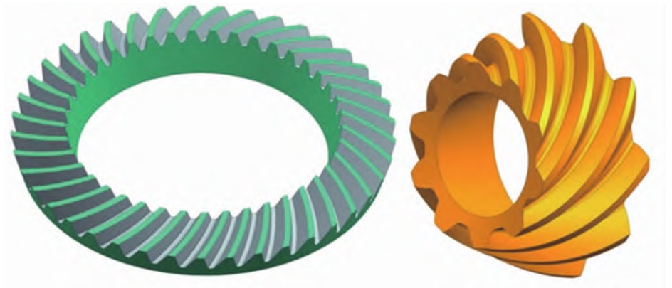
RV reducer, as an excellent speed reduction mechanism, is widely used in various fields such as industrial robots, machine tools, and medical testing equipment. The common structure of RV reducer is shown in Figure 1.1. It adopts a cycloidal pin gear planetary gear mechanism, which has the advantages of high part stiffness, small contact stress during movement, and high machining and installation accuracy of parts. In addition, RV reducer also has the characteristics of compact structure, high acceptable torsional stiffness, and low vibration and noise of the cycloidal pin gear planetary gear transmission structure, making it the most widely used precision equipment and instrument reducer.
The cycloidal gear is the core component in the RV reducer. It realizes transmission and deceleration by meshing with the pin gear in the reducer. Therefore, the accuracy of the tooth profile of the cycloidal gear directly determines the transmission accuracy of the reducer. However, at present, it is still a challenge to efficiently manufacture high-precision cycloidal gears in China. Therefore, how to solve the precision machining of cycloidal gears has become an important issue that needs to be addressed.
At present, the main method for efficient mass production of cycloidal gears is hobbing. However, due to the presence of multiple hollow hole structures on the cycloidal gear for assembly, the stiffness of the cycloidal gear is insufficient. During hobbing, excessive cutting force may cause workpiece deformation, resulting in a decrease in the dimensional accuracy of the cycloidal gear and affecting the transmission performance of the RV reducer. The cycloidal gear.
In addition, the hollow hole structure on the cycloidal gear makes the stiffness distribution of the cycloidal gear uneven, which may cause inconsistent deformation during hobbing, resulting . Therefore, how to predict the cutting force during the hobbing process of the cycloidal gear and obtain the deformation law of the gear caused by the hobbing cutting force is the key to the development of the RV reducer manufacturing technology in China.
1.2 Research Status at Home and Abroad
1.2.1 Research Status of Hobbing Cutting Force
At present, many scholars at home and abroad have conducted research on the cutting force of hobbing and achieved fruitful results. The models can be summarized into the following two types: (1) Research on hobbing cutting force based on unit cutting force coefficient calculation; (2) Research on hobbing cutting force based on finite element simulation.
1.2.1.1 Research on Hobbing Cutting Force Based on Unit Cutting Force Coefficient Calculation
This mechanical model is mainly applied to various turning, milling, and hobbing scenarios. Since turning and milling belong to three-dimensional free cutting, researchers can freely choose processing parameters such as cutting speed, feed rate, and cutting feed direction. Therefore, the main parameters affecting the cutting force, such as cutting width and cutting depth, are highly controllable. Therefore, the cutting force can be expressed as a coefficient function of processing parameters such as cutting width and cutting depth. Ce et al. derived the hob tooth equation based on the meshing motion process of the circular arc gear and the rack, and studied the generating method process of circular arc gear hobbing on a two-dimensional plane using CAD software to determine the cutting force coefficient based on the two-dimensional chip shear area. Li et al. established a linkage model and a motion model for non-circular gear hobbing, studied the fluctuation law of the cutting force and the change law of the chip area during the non-circular gear hobbing process, established the fluctuation trend of the hobbing force characterized by the undeformed chip volume based on the unit cutting force coefficient method, and compared the cutting force fluctuation characteristics of different hobbing models. Zheng et al. studied the milling process of hardened alloy steel molds, analyzed the volume of milling chips, established the milling force based on the cutting force coefficient, and analyzed the displacement deflection problem of the tool when feeding along the path caused by the milling force. Efstathiou et al. modeled and analyzed the manufacturing process of bevel gears based on the BevelSim3D algorithm, obtained the three-dimensional kinematic models of face milling and face hobbing, characterized the volume and shape of the undeformed chip, optimized the geometric entity tooth surface geometry, analyzed the shape of the solid chip geometry, and obtained the cutting force based on the cutting force coefficient. They also studied the influence of the finishing allowance on the cutting force coefficient under the finishing parameters and corrected the bevel gear hobbing cutting force based on the cutting force coefficient. Tsouknidas et al. optimized the cutting force coefficient in the software FRDYN based on numerical analysis, improved the calculation efficiency of the software for the cutting force within the range of hob chip thickness below 0.1mm, and optimized the coefficient equation between the cutting speed and the cutting force, improving the application range of the FRDYN software. Kyratsis et al. developed the manufacturing simulation software SPARTApro based on the FRDYN software and the cutting force micro-element method. This software simulates based on mechanical kinematics, uses the tool contour to perform Boolean operations on several planes to simulate the machining process, and further provides the ability to determine the characteristic chips and improve the hobbing process. Chara et al. based on the exponential mechanical model and the Terashimak hobbing cutting force modeling method, conducted finite element simulation of the cutting process of involute spur gears and involute helical gears, and predicted the cutting forces of the two gears. Brecher et al. replaced the blank and hob in the hobbing process with a motion model combined with the cutting force micro-element method to predict the instantaneous cutting force at a certain moment in the cutting cycle. Mattias et al. analyzed the cutting force and hob wear behavior during the hobbing process, established a mathematical model based on the micro-element force, and studied the wear mechanism of the hob caused by the periodic change of the cutting force. Abood analyzed the chips generated by hobbing, modeled the unit cutting force model by the analytical method, and predicted the cutting force by combining the chip geometric model. Han Jiang et al. studied the hobbing cutting force of oval gears based on the unit cutting force method, proposed a method for extracting the undeformed chip of non-circular gear hobbing, established the corresponding cutting force model, and analyzed the fluctuation law of the cutting force.
1.2.1.2 Research on Hobbing Cutting Force Based on Finite Element Simulation
Since hobbing has a more complex motion relationship than turning and milling and the wear mechanism of the tool is also different from that of turning and milling tools due to the characteristics of three-dimensional non-free intermittent cutting. With the improvement of the finite element analysis theory and the development of computer technology, some scholars have used the finite element analysis method to physically simulate hobbing.
Liu et al. simulated the chip formation process and chip flow characteristics of hobbing using the finite element analysis method and successfully visualized the extrusion phenomenon between the chip and the tool during the chip flow process on the computer. At the same time, the researchers considered the physical properties of the material, enabling the finite element simulation to reveal the laws of cutting force, stress and strain in the machining area, and temperature gradient change during the hobbing process. Deng et al. adopted the whole machine finite element method for the force-induced error model in high-speed hobbing, combined the main geometric elements and physical boundaries in the machine tool, established a method to map the system force-induced error to the tooth surface normal error, obtained the mapping relationship between different types of force-induced errors and the hobbing accuracy, analyzed the theoretical and actual tooth surfaces using the numerical calculation method, and established a tooth profile compensation method. Stark et al. determined the heat flux density that causes thermal deformation in the gear machining process, simulated the chip formation mechanism in hobbing through the integrated simulation environment, and predicted the cutting temperature and stress during the cutting process. Zou et al. used the three-dimensional rigid-viscoplastic finite element method to simulate the chip formation process to study the chipping phenomenon of high-speed steel hobs, clarified the mechanism of chip extrusion, and obtained the physical quantities such as stress and strain during the chip formation process. Brimmers et al. proposed a geometric penetration calculation method in the finite element simulation, established multiple scale models for the hobbing process, effectively confirmed the force and thermal loads in hobbing, predicted the hobbing cutting force and the cutting temperature on the rake face of a certain gear through the orthogonal method of cutting parameters. Wang Peng et al. studied the influence of the cutting force and cutting heat on the tool life in the shaving process of the pin gear housing, established a three-dimensional model of the shaving tool, modeled the shaving process through finite element simulation, obtained the cutting force and cutting heat, and established a tool wear model with the mean and amplitude of the shaving cutting force as parameters. Nie Xianwei used the ABAQUS software to simulate the milling process of spiral bevel gears, obtained the results of the cutting layer morphology and stress distribution, and analyzed the influence laws of different cutting parameters on the two. Liao Congjian used the AdvantEdge software to study the cutting performance of different structural designs of the cutting edge shape by using different rake angles and cutting parameters for high-speed bevel gear cutting simulation, and verified the correctness of the simulation results with the experimental results and the calculation results of the cutting force prediction model. Zhou Li calculated the cutting state of the hob teeth on the hob using the Deform simulation software based on the hobbing cutting space formation model, verified the correctness of this model with the chips obtained from the experiment, and analyzed the changes of the hobbing cutting temperature, cutting force, and gear stress distribution during the hobbing process using this model. Guo Qian simplified the hobbing process as a flying cutter milling process, analyzed the influencing factors of the cutting force through orthogonal simulation experiments and orthogonal experiments, and preliminarily revealed the application mechanism of high-speed dry machining in hobbing. Liu et al. simulated the cutting force in the hobbing process using the finite element software Third Wave AdvantEdge and verified it through a single-tooth milling force test.
In summary, scholars at home and abroad have studied the hobbing cutting force based on the cutting force coefficient method and the finite element method for various machining scenarios and machining objects, studied the hobbing cutting force models of various cutting force coefficients and micro-element methods, and conducted simulations with different tools, cutting parameters, and structural designs to analyze the hobbing cutting force.
1.2.2 Research Status of Hobbing Cutting Deformation
Due to the compact structure of the RV reducer, the ratio of the outer diameter to the gear thickness of the cycloidal gear can usually reach about 15:1. At the same time, due to the design of the RV reducer structure, the cycloidal gear has multiple circular holes and trapezoidal holes, resulting in a relatively weak structural rigidity of the cycloidal gear. Therefore, the research on the machining deformation of the cycloidal gear can refer to the research on the machining deformation of thin-walled parts. The prediction of the machining deformation of thin-walled parts has always attracted much attention, and many scholars have proposed many research methods: (1) Prediction of workpiece deformation based on the finite element method; (2) Prediction of deformation based on the neural network algorithm; (3) Analysis of machining deformation based on theoretical calculation and actual machining.
1.2.2.1 Prediction of Workpiece Deformation Based on the Finite Element Method
Zhang Guang et al. modeled the face gear turning process using the finite element simulation method, analyzed the cutting speed, cutting depth, and feed rate in the machining parameters, and obtained the influence of the cutting parameters on the tooth surface deformation of the face gear. Liu predicted the machining deformation of a thin-walled part with a cantilever using the finite element analysis method. Feng Peiyao et al. studied the milling deformation of involute straight bevel gears, established a model of structural stiffness-stress-deformation amount based on the finite element simulation method, and effectively predicted the machining deformation of the gear blank. Bi Yunbo et al. established a milling model of a certain aviation thin-walled part using the finite element simulation software, predicted the deformation of the thin-walled part, and verified the accuracy of the model through experiments. Chen Ziliang established a simulation model with symmetric structure, stress, and machining process for material removal based on the three-dimensional modeling software and the finite element simulation software, and predicted the machining deformation of the workpiece caused by stress release and coupling stress residual during the machining process. Shao et al. modeled the quenching process of the gear using the finite element method and the multi-field coupling theory, simulated the deformation caused by the uneven martensite due to the uneven cooling rate of the gear caused by the asymmetric structure, and verified the accuracy of the deformation through experiments. Chen et al. developed a model for the multi-layer cutting finishing technology of thin-walled parts based on the finite element method. After considering the coupling relationship of the interlayer deformation of the thin-walled parts, the researchers predicted the deformation of the thin-walled parts caused by the milling force. Wu et al. modeled the milling process of a certain thin-walled part using the finite element simulation, proposed a new prediction model for the cutting heat and the tool flank wear after considering the force-thermal coupling, and improved the overall prediction accuracy of the thin-walled part milling simulation. Kang et al. modeled a workpiece-fixture system using the finite element simulation, considering the problem of reduced workpiece-fixture system stiffness caused by the gap between the fixture and the workpiece due to the contour error, and predicted the deformation of the workpiece-fixture system under various clamping forces.