
The rapid development of China’s industry requires gears with long service life, fatigue resistance, and high reliability, which requires higher surface hardness of gears
Surface integrity. Among many finishing technologies, barrel finishing has the characteristics of reducing the surface roughness of workpieces, refining the surface processing texture of workpieces, improving the residual stress on the surface of workpieces, and being easy to process complex-shaped parts with low cost. Therefore, it is widely used in the finishing of parts. Spindle barrel finishing is a common gear finishing process that can improve the surface integrity of gears, remove burrs, round corners, reduce noise, improve transmission efficiency, and obtain isotropic tooth surfaces. In spindle barrel finishing, the contact force of the workpiece surface and the impact velocity of particles have a significant impact on the processing effects of material removal, residual stress, and roughness of the workpiece. Many scholars at home and abroad have conducted research on the contact force and impact velocity of particles. Through experiments, it has been verified that the product of particle contact force and particle impact velocity is proportional to the material removal rate of the workpiece surface. Using a dynamic force sensor, the influence of particle size, workpiece installation position, and contact force on the surface processing effect of the workpiece was tested. It was found that when the particle diameter is small and the depth of workpiece penetration is small, the processing effect is best. The strain gauge was used to measure the contact force of the workpiece in spindle barrel finishing, and it was proved that there is a strong correlation between the particle accumulation height above the workpiece and the contact force. The higher the accumulation height, the stronger the correlation between contact force and material removal rate The greater the force, the higher the accumulation height of particles on the workpiece surface in the spindle-type rolling finishing process. Experiments have shown that the higher the accumulation height of particles on the workpiece surface, the greater the normal stress and tangential stress on the surface. It was also found that conical particles can cause greater stress on the workpiece surface. Some scholars have also used high-speed cameras to measure and analyze the velocity of particles in the spindle-type rolling finishing process. By measuring and calculating the tangential velocity of particles at the interface of particle groups, a submerged particle tracker was developed to measure and analyze the velocity of particles within the particle group. As a typical free abrasive finishing technology, compared with other finishing methods, the processing technology of rolling finishing is mainly based on experience and requires multiple trials and error testing. With the development of 3D printing, the finishing of non-standard and complex structural parts has gradually become a trend, so it is particularly important to predict the optimal processing technology for finishing. At present, most of the research related to spindle-type rolling finishing is based on direct measurement of contact force and motion velocity of particles, but there is limited research on the interface between particles and workpiece, making it difficult to clarify the behavior of particles. Modeling and predicting changes in surface roughness of parts in rolling finishing technology remains a major challenge.
Particle flow field analysis
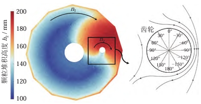
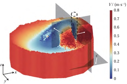
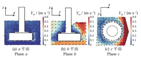
For the spindle-type roll grinding finishing process without workpiece, the rotational motion of the roller causes the upper interface of the particle group inside the cylinder to appear as a paraboloid. When After placing the workpiece, the flow of particles is blocked by the workpiece, breaking the original flow pattern, and particles accumulate at the front end of the workpiece, resulting in a difference in the height of the particle accumulation at the front and rear ends of the workpiece, which affects the contact force between the particles and the workpiece. The figure shows the cloud diagram of the particle group’s upper boundary surface height under the condition of =80 mm and =30 r/min. From the figure, it can be seen that the moving particles are blocked by the gear and the tool shaft, resulting in a higher particle accumulation than the stationary state (the stationary state accumulation height is 140.00 mm) in the region of −150° to 120° at the front end of the gear. The maximum accumulation height is 192.23 mm. Among them, there is a significant decrease in the particle accumulation height in the regions of −150° to −90° and 90° to 120°, and a hole area below the stationary accumulation height is generated in the region of 120° to −150° at the rear end of the gear, which is on the gear’s moving wake. The maximum height difference between the front and rear ends of the gear reaches 70.00 mm. The figure shows a cloud diagram of particle motion velocity. Due to the collision between the particle group and the workpiece, the kinetic energy of particles at the front end of the gear decreases and changes direction. Some kinetic energy is converted into potential energy for particle climbing, while another part is converted into internal energy for friction between particles and the gear. At the rear end of the gear (in the region of 90° to −90° in the figure), potential energy is converted into kinetic energy, causing particles to accelerate downward. As shown in the figure, sections with a thickness of 6 mm were selected from three planes (the central planes in three directions) of gear a, b, and c to observe the flow of particles near the gear.
Force analysis of particles in tooth contact
When h1 = 80 mm, the number of particle contacts during one rotation of the gear is shown in Figure 8, with contact particles as the reference object. When n1
When the speed of rotation is 30 r/min, the variation of the normal contact force of the gear surface with time during one rotation period is shown in Figure 9. It can be seen from the figure that the variation of the number of contact particles on the gear surface is a gradual increase, then a constant period, and then a gradual decrease. However, the variation of the number of contact particles on the gear surface under different working conditions is not the same. When the speed of rotation is lower and the depth of penetration is shallow, there are fewer particles remaining in the tooth groove during the particle outflow stage. This is because when the speed of rotation is too low, the centrifugal force provided by the gear rotation to the particles is small, and secondly, when the rotating speed of the roller is slow, the particles impacting on the gear have a smaller wake region at the rear end of the gear, allowing the particles to fill into the tooth groove in time. Although the number of contact particles on the gear surface varies depending on parameters, the number of particles in the stable filling stage is roughly the same, ranging from 30 to 40. From the perspective of normal contact force on the gear surface, this difference is particularly significant. The period from 0 to 0.3 T is the particle inflow stage, during which although the number of contact particles on the gear surface increases rapidly, there is a lag in the increase in normal contact force. The normal contact force increases significantly only when there are 30 contact particles, and most of the time it is almost zero. The period from 0.3 to 0.7 T is the stable filling stage of particles, during which the normal contact force on the gear surface increases rapidly in a short period of time and then maintains a large normal contact force until particles start to flow out of the tooth groove rapidly. The period from 0.7 to 1.0 T is the particle outflow stage, during which the normal contact force on the gear surface decreases rapidly and remains close to zero for most of the time. Under five different working conditions simulated by discrete element method, the average normal contact force on the gear surface during stable filling stage of particles is 22.45 times that during particle inflow stage and 26.24 times that during particle outflow stage, indicating that stable filling stage is a major action stage for particles on gears.
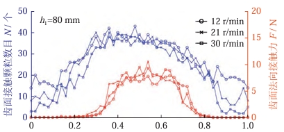
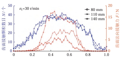
As the speed increases, the normal contact force on the tooth surface slightly increases, with a small difference. When the speed increases by 150% from 12 r/min to 30 r/min, the normal contact force on the tooth surface increases by 18%. However, as can be seen from the figure, as the depth of embedment increases, the normal contact force on the tooth surface significantly increases. When the depth of embedment increases by 75% from 80 mm to 140 mm, the normal contact force on the tooth surface increases by 76%. Therefore, it can be shown that the force of particles on the tooth surface is greatly affected by the depth of embedment of the gear and less affected by the speed.
Analysis of contact particle velocity
The main stage of the particle’s effect on the tooth surface is the stable filling stage, so the particles that are in contact with the tooth surface during this stage are selected as the reference objects (0.4 rotation cycles of the gear) to explore the influence of speed and embedding depth on the relative motion speed of particles. Figure 11 shows the variation of particle velocity relative to the tooth surface during the stable filling stage. The figure shows the average relative velocity change of particles at different speeds when the workpiece embedding depth is 80 mm. It can be seen from the figure that as the speed increases, the average relative velocity of particles in different regions of the tooth surface increases linearly, from 12 to 30 r/min, increasing by 148% to 151%, of which the tooth surface increases by 148%. It can also be seen that due to the influence of the tooth groove structure, the average relative velocity of particles on the upper tooth surface is significantly greater than that on the lower tooth surface, with the upper tooth surface being 1.35 to 1.40 times that of the lower tooth surface at different speeds. Figure 11b shows the variation of average relative velocity of particles at different depths when the roller speed n1= 30 r/min. It can be seen that as the workpiece embedding depth increases, the average relative velocity of particles does not increase significantly, and different regions of the tooth surface increase by 2% to 9% at 80-140 mm, of which the tooth surface increases by 4%, and the difference between upper and lower tooth surfaces still exists. At different embedding depths, the upper tooth surface is 1.35 to 1.45 times that of the lower tooth surface. Therefore, it can be shown that the relative velocity of particles and tooth surface is less affected by gear embedding depth and more affected by speed. There is unevenness between upper and lower tooth surfaces, and the average relative velocity of particles on the upper tooth surface is 1.35 to 1.45 times that on the lower tooth surface. Changing speed and workpiece embedding depth have little effect on this unevenness. Combining Section 3.2, it can be concluded that increasing depth mainly affects the contact force between particles and tooth surface, while increasing speed mainly affects the relative motion speed of particles and tooth surface.
Conclusion
For the spindle-type rolling and grinding finishing process, a discrete element simulation method is used to describe the contact between the entire particle group and the tooth surface in the spindle-type rolling and grinding finishing process The flow characteristics of particles, the influence of depth and speed on the relative velocity and contact force of particles contacting the tooth surface, and the experimental verification are analyzed. The following conclusions are drawn Conclusion:
(1) The flow and force of particles in the gear tooth groove exhibit periodic changes, which can be divided into three stages: particle filling stage, stable particle filling stage, and particle flow stage There are 3 stages in the particle outflow stage, in which the stable particle filling stage is the main stage of the action of particles on the gear. The average normal direction of the tooth surface in the stable filling stage The contact force is 22.45 times higher in the particle filling stage and 26.24 times higher in the particle outflow stage.The increase in the depth of gear embedment mainly affects the contact force between particles and the tooth surface. When the embedment depth increases by 75%, the normal contact force on the tooth surface increases by When the gear and roller speed increases by 150%, the relative motion speed of the particles and the tooth surface increases by 148%, and the normal contact force of the tooth surface increases by 18%.
(3) The spindle-type rolling and grinding finishing process can be used to process the entire area of the tooth surface, but there will be a relative motion speed between the force applied to each part of the tooth surface and the particles In the case of uneven distribution, the contact force on the upper tooth surface is 1.52-1.88 times that on the lower tooth surface, and the average relative motion speed of particles on the upper tooth surface is which is 1.35-1.45 times that of control.
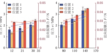
(4) Increasing the gear embedment depth can reduce the axial processing variability of the gear. When the embedment depth is increased from 80 mm to 140 mm, the variation along the axis decreases The roughness reduction rates of the upper and lower tooth surfaces changed from 17% and 36% to 62% and 55%, while changing the speed and depth of immersion had a significant effect on the machining along the tooth profile direction The difference in changes is not significant.